This article describes how the Handyscope HS4 DIFF USB oscilloscope was used in combination with the CAN decoder I/O and J1939 decoder I/O in the TiePie engineering Multi Channel oscilloscope software to solve SAE J1939 communication problems in a Diesel engine driven firewater pump system on an offshore gas platform.
Introduction

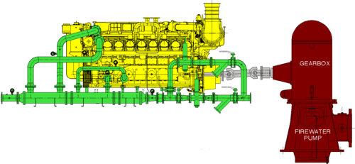
A new offshore gas processing plant is built 135 km north west of Karratha (Australia) in the Indian ocean. Essential safety measures on offshore facilities include reliable firewater pumps that can deliver enough water in case of a fire. The new platform is equipped with two mechanical firewater pumps. Each unit consists of:
- a Caterpillar D 3516 C marine engine, a 16 cylinder electronically controlled (ADAM 3) Diesel engine delivering 2350 kW at 1800 RPM, supplied by PON-CAT. In emergency situations, this engine is set to "run to destruct" mode. Only an emergency stop or overspeed will shut down the engine, all other signals will only set alarms.
- a gearbox with 4:7 ratio
- a Sulzer pump, capable of displacing 4600 m3 water per hour (1278 l/s), at 1.2 MPa (12 bar) pressure, when the engine runs at 88% power
- a Topec control panel with Modbus and CAN bus (SAE J1939) communication, a touch screen for operation and an interface with a Distributed Control System (DCS) on the platform.
Problem description
The installations that are used on a new platform are manufactured all over the globe. When building a platform these installations or installation parts are gathered and combined to one big offshore facility. After the initial connection the commissioning stage starts and all the links between the different installation components are tested for their correct functionality. Nowadays these links consist of sophisticated bus systems like Profibus, Modbus, CAN bus, J1939, HART or fieldbus. When troubleshooting these systems a digital multimeter is no longer sufficient to diagnose and pinpoint a problem. The following example will show how potential problems and cause can be pinpointed by use of a oscilloscope.
One of the problems that was found during commissioning of the firewater pump system was that two values of the engine status were not properly transferred to the DCS. As a result, this part of the DCS / firewater pump system couldn't be signed off on.
The engine is equipped with many sensors, that give their analog signals to the Engine Control Module (ECM). It uses these signals to control the engine and to signal the engine state to the operator, via the control panel. The ECM communicates with a control panel over a CAN bus using the J1939 protocol. The control panel receives the signals and presents them to the operator via the screen and transfers them to the DCS using a modbus communication link.
The values of these particular sensors were available in the ECM, but did not show up on the control panel. Other sensor values did however arrive properly, so it was concluded that the CAN bus with J1939 protocol was functioning properly. Therefore, either the requested values were not available on the bus, or there was something wrong in the control panel.
Measuring
To find out whether the J1939 values were available on the CAN bus, the bus contents had to be examined. SAE J1939 is a protocol on top of the CAN protocol and J1939 messages are encoded in extended CAN messages. A CAN bus uses differential signal lines to serially transmit CAN messages.
A Handyscope HS4 DIFF was connected to the CAN bus. With its differential inputs it can be connected directly to the differential lines of the CAN interface to measure the differential communication signal. The CAN decoder I/O in the Multi Channel oscilloscope software was used to analyze the CAN signals and decode the CAN messages. The J1939 decoder I/O was then used to decode the J1939 specific information from the CAN messages and display the required values.
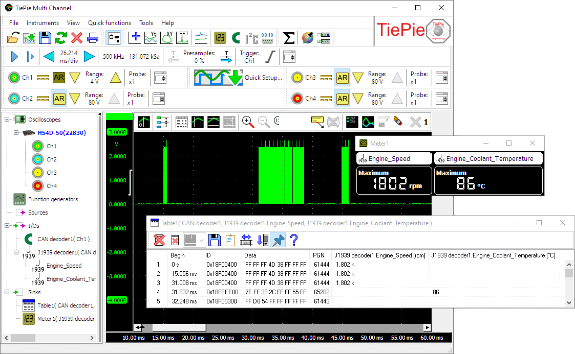
Figure 4 shows the measured differential CAN signal as measured by the Handyscope HS4 DIFF. The decoded CAN messages are displayed in the table. The J1939 values decoded from the CAN messages are added to the table and also displayed in the meter display.
Cause and solution
The decoded J1939 values corresponded to the values that were available in the ECM, so the proper values were available on the CAN bus. The control panel was then examined and it turned out that the communications PLC of the control panel was not properly setup, causing these particular messages not to be displayed. After correcting the setup, the problem was rectified and the values were displayed properly on the control panel and DCS. As a result the system could be signed off as tested and functional.
Conclusion
When troubleshooting serial communication bus systems like CAN and J1939, proper tools have to be used. A multimeter is not sufficient, as it can only show whether an electrical connection is available. Using the Handyscope HS4 DIFF with the Multi Channel oscilloscope software, the electrical CAN signals can be measured directly and decoded into the actual values that are transmitted. At the same location, the Handyscope HS4 DIFF was also used to check the amplitude of a magnetic pickup unit (MPU), to verify the correct distance from the ring gear and the quality of its teeth, as well as for other measurements. Its versatility, compact size and light weight make the Handyscope HS4 DIFF an ideal instrument for offshore service engineers who often travel by plane, helicopter and boat.
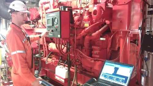
Photographs and information by Jurgen van der Veen, international commissioning engineer Topec B.V.