Contents
Introduction
The protocol analyzing blocks in the Multi Channel oscilloscope software expect signals that behave digital: the level of the signal is either "high" or "low" and the transition from one level to the other should happen instantaneously, taking no time. The exact values for "high" and "low" depend on the system that is being analyzed.
In the real world, nice clean signals do not always appear, the actual values for "high" and "low" may differ from the expected values and they can also vary instead of being stable. And there can be noise on the signals.
Although the analyzers in the Multi Channel oscilloscope software are designed to be tolerant on signal quality, sometimes the signals are too bad for the analyzer to be able to decode the information automatically.
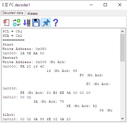
The measurement below shows the SCL and SDA signals from an I²C communication. The signals contain a lot of noise and many glitches. Also the "High" and "low" levels are not entirely correct.
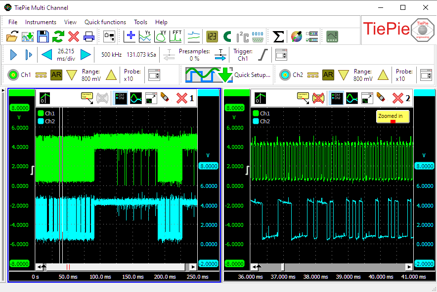
This causes the I2C decoder sink to fail decoding the transmitted information as can be seen in the Restart and the various No Ack indications.
Cleaning the signals
In order for the I2C decoder sink to decode the signals properly, the signals will have to be cleaned up, removing the noise and glitches. Both the Clock and the Data signal will have to be cleaned independently. The easiest way to do this is to setup the cleaning method for one channel and once it's properly setup, clone the used object for the second signal.
First attempt: filtering

An obvious solution to the problem seems to be to put the signal through a Filter I/O in Low Pass mode, that way removing the unwanted noise and glitches. However, the low pass filter is a first order filter, which is not very steep. A proper digital signal has very steep edges. Filtering a digital signal with a first order filter will make the edges of the signal slower, as can be seen below. The slower edges make it harder for the I2C decoder to properly detect the edges in the signal. In our situation, the I2C decoder is still failing to decode the signal.
Second attempt : limiting

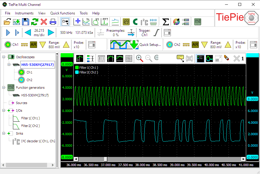
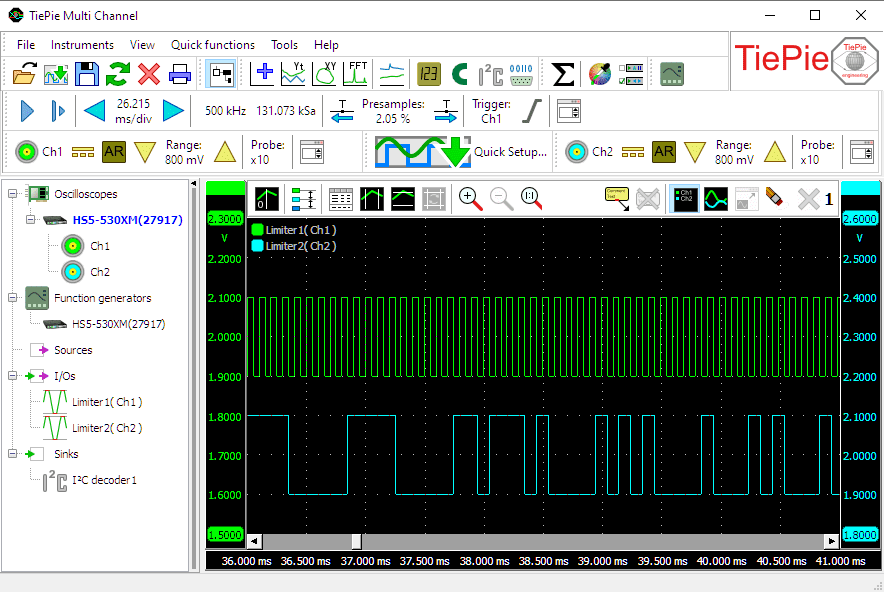
Another way to remove unwanted parts from a signal is by using the Limiter I/O. It uses a user settable lower and a higher limit (clip range) and all signal parts that exceed the range are clipped to that range.
To use the Limiter I/O to clean up these signals, the clip range must be set to levels that ensure that all signal parts that are supposed to be high clip at the higher level of the clip range and all signal parts that are supposed to be low clip at the lower level. In our signals, the high parts of the signals never go below 2.2 V and the low parts of the signals never go above 1.5 V. To be save we set the lower limit of the clip range to 1.9 V and the higher limit to 2.1 V and connect the Limiter I/O to our channel. As can be seen in the image below, this gives very clean, crisp digital signals.
Correct the levels

Although the signals are now clean, all noise and glitches are removed, the signals are now wrong in level. Proper I2C signals are either between 0 and 3.3 V or between 0 and 5 V and our signals are between 1.9 and 2.1 V, which is not recognized by the I2C decoder.
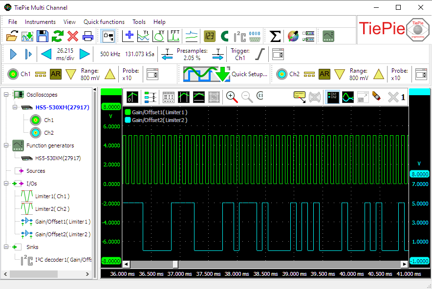
To correct the levels of the signal, create a Gain/Offset I/O and connect that to the Limiter I/O. The Gain/Offset I/O can apply an offset to the signal and apply a gain to the signal.
Correct the offset
The signal from the Limiter I/O ranges from 1.9 to 2.1 V, while the lowest value should be 0 V. To compensate for that, set the Input Offset of the Gain/Offset I/O to -1.9 V. The output signal of the Gain/Offset I/O ranges now from 0 to 0.2 V.
Correct the amplitude
To let our signal range from 0 to 5 V, instead of from 0 to 0.2 V, it needs to be amplified 25 times. Setting the Gain of the Gain/Offset I/O to 25 will take care of that.
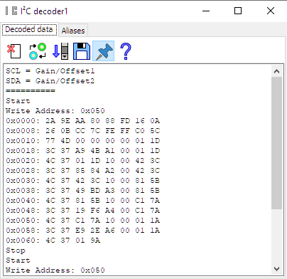
Decoding successful
We now have perfect I2C signals, free of noise and glitches and with the correct levels.
The I2C decoder sink is now capable of decoding the signals without problems, as can be seen below.