Contents
Introduction
To measure a current with a TiePie engineering measuring instrument with voltage inputs, the current has to be converted to a voltage related to the current. One way to do this, is to add a known resistor in the current path and measure the voltage over the resistor. This method has several drawbacks:
- The existing circuit has to be broken to add the resistor
- Adding a resistor to the circuit may affect the circuit
- Unless a differential input is used, it is not always possible to measure directly over a resistor in a circuit.
A better way to measure a current is using a current clamp, since it does not have these disadvantages.
Current clamps
A current clamp offers a way to measure the current in a conductor without the need to break the circuit. The current can be measured while maintaining a galvanic isolation between the measuring instrument and the circuit under test.
TiePie engineering offers three different current clamps:
| Model | Ranges | |
|---|---|---|
| Current clamp TP-CC80 | 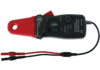 |
20 A / 80 A switchable range, AC and DC |
| Current clamp TP-CC400 | 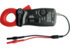 |
40 A / 400 A switchable range, AC and DC |
| Current clamp TP-CC600 | 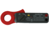 |
200 A / 600 A switchable range, AC and DC |
Connecting the current clamp
To measure a current using a current clamp, connect the current clamp to one of the inputs of the oscilloscope. The TiePie engineering current clamps have 4 mm female banana sockets. Connect the red socket to the positive terminal of the input and the black socket to the negative terminal.
Set the selector switch from the OFF position to the required input range of the current clamp. The power LED will light to indicate that the current clamp is switched on.
While the current clamp jaws are closed, press the ZERO button to reset the current clamp to zero. This will remove any offset, caused by residual magnetism remains in the core of the jaws. During zeroing, no current should flow through the clamp, so remove any wires from the clamp, or make sure no current is flowing through them.
Clamp the jaws around the current carrying conductor(s). Always make sure the jaws are tightly closed.
Setting up the input channel
The current clamp outputs a voltage that is related to the current it measures. The channel's probe gain setting is used to convert the measured voltage to the original current value. The channel's unit setting is used to display the values in A.

To do that, go to the channel toolbar and select the correct probe and range setting using the Probe button. This will automatically set the channel's probe gain setting to the correct value and the channel's unit to 'A'.
Measuring DC current
When measuring DC current, it is important to zero the current clamp before clamping it around the conductor. Always press the Zero button with fully closed jaws.
In case of measuring a DC current, the polarity of the output voltage depends on the current direction through the jaw of the current clamp.
| Model | Current direction1 | Output voltage |
|---|---|---|
| Current clamp TP-CC80 | Top to bottom | Positive |
| Current clamp TP-CC400 | Bottom to top | Positive |
| Current clamp TP-CC600 | Bottom to top | Positive |
1. Top of the current clamp is the side with the range selector switch.
Leakage detection
When more than one conductor is placed within the jaws of the current clamp, the sum of all currents flowing through the conductors is measured. Since a current clamp is direction sensitive, currents flowing in the opposite direction will be subtracted.
This makes it possible to detect a current leakage in a device. Place the clamp around all power conductors going to the device, except the earth. The sum of all currents should be zero. When the sum is not zero, there must be a current leak to earth in the device.