Contents
Introduction
I2C (Inter-Integrated Circuit) is a serial bus, that is used to exchange data with low-speed peripherals. I2C uses two bi-directional lines, serial data (SDA) and serial clock (SCL). Typical voltages used are +5 V or +3.3 V. The most common I2C bus modes are the 400 kbit/s fast mode, the 100 kbit/s standard mode and the 10 kbit/s low-speed mode. A high speed mode of 3.4 Mbit/s is also available.
I2C uses a 7 bit or 10 bit address, depending on the device, with 16 reserved addresses, which means that a maximum of 1008 nodes can communicate on the same bus. Two types of nodes are possible: master and slave. I2C devices use a dedicated protocol to communicate with each other.
When devices on a I2C bus are not communicating properly, something must be wrong and the error has to be found. Measuring the electrical parameters of the two signals in the I2C bus can be done easily with an oscilloscope. But, when the electrical parameters are all OK, the signals have to be analyzed, to check if the communication protocol is implemented properly.
Requirements
Measuring
To measure I2C signals, a measuring instrument with at least two channels is required. The maximum frequency on the I2C bus depends on the bus type, the instrument must sample at at least twice the maximum speed on the bus, but preferable five to ten times higher, on both channels. For a 100 kbit/s bus that would mean a minimum sampling frequency of at least 1 MHz on both channels. I2C uses either 3.3 V or 5 V, so the instrument should be able to measure voltages between 0 and 5 V. Since data transfers can be long, a long record length is preferred to capture the communication.
The WiFiScope WS6 DIFF, WiFiScope WS6, WiFiScope WS5, WiFiScope WS4 DIFF, Handyscope HS6 DIFF, Handyscope HS5, Handyscope HS4 DIFF, Handyscope HS4 and the Handyscope HS3 are suitable instruments to measure I2C signals.
Analyzing
To examine the communication protocol in the measured signals, the various pulses on both signals have to be examined and their sequences have to be converted in I2C commands.
The TiePie engineering Multi Channel oscilloscope software is capable of analyzing the I2C communication protocol, using the I2C decoder.
In this example, a Handyscope HS5 is used to measure I2C signals on an I2C EEPROM that is being accessed.
Setting up the hardware
First the Handyscope HS5 is connected to the computer and the Multi Channel oscilloscope software is started.
Now connect Ch1 to the Serial Clock signal of the I2C bus and Ch2 to the Serial Data signal of the I2C bus. The ground terminals of the two input channels must be connected to the same ground as the I2C bus uses.
Setting up the software
Setting up the input channels
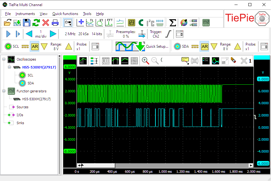
We are using Ch1 to measure the Serial Clock signal (SCL) and Ch2 to measure the Serial Data signal (SDA). To simplify recognition of the signals, they can be given a descriptive name (alias). To change the alias of a channel, right-click the channel in the object screen and select Alias... and enter the required alias. Give Ch1 the alias "SCL" and Ch2 the alias "SDA".
Signals on the I²C bus lie between 0 V and either +3.3 V or +5 V. Therefore, set the channel input coupling of both channels to "DC" and set the input sensitivity of both channels to "8 V" full scale. That way both signal levels can be measured properly.
Setting up the time base
The I2C signals in our example are measured on a 100 kbit/s bus, and can therefore be up to 100 kHz in frequency, which means that the minimum required sampling frequency must be 200 kHz. However, this results in only 2 samples per period, barely enough to recognize the signal but not enough to analyze it properly. Therefore, set the sampling frequency to at least 1 MHz.
Since I2C communication can take several milliseconds, a long record length is preferred, to capture as much as possible of the communication. In this example, a relative short communication is measured, therefore the record length is set to 20000 samples. When a longer communication is expected, set the record length to a longer value, e.g. 100000 samples.
Setting up the trigger
Both SCL and SDA are high in idle state. When a communication starts, first the SDA line is made low. Therefore, select Ch2 as trigger source, set the trigger mode to "falling edge" and set the trigger level to a value half way the signal, e.g. 1.5 V. Set the trigger hysteresis to e.g. 0.5 V. A trigger will now occur when Ch2 measures a falling edge, where the signal is initially above +2 V and drops below 1.5 V.
Setting up the I2C decoder
To analyze the I2C signals, the I2C decoder I/O is used. Create one by clicking I/Os in the object screen and then Decode.
The I2C decoder requires two sources to be connected, the first source that is connected is treated as SCL, the second signal is treated as SDA. First drag Ch1 on the I2C decoder and then drag Ch2 on the I2C decoder.
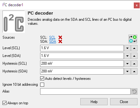
The I2C decoder settings window, which is opened by double-clicking the I2C decoder I/O, will now display which source is connected to the SCL input and which source is connected to the SDA input of the decoder.
When the inputs are connected to the wrong sources, a click on the
 Swap inputs button will swap the inputs.
The I2C decoder can analyze both 3.3 V I2C buses and 5 V I2C buses. All signal levels above Level are considered a logical "1" and all signal levels below Level - Hysteresis are considered a logical "0". The decoder can detect a Level and Hysteresis for both signals individually, based on the measured data or the user can set voltages that will be used as level and hysteresis. Usually, Auto level and hysteresis will do, so enable Auto detect level / hysteresis.
To display the decoded I2C messages, a Table sink is used. Create one by clicking Sinks in the object screen and then Table. Connect the I2C decoder to the table sink by dragging it on the table sink in the object screen .
Ready to measure
Now both input channels and I2C decoder are configured, a measurement can be performed and analyzed.
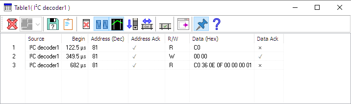
The I2C signals shown in the screen shot above are from communication with an EEPROM. They are converted by the I2C decoder into the following commands:
To clear the table for a new measurement, press the
 Clear button.
The I2C decoder can show more information in columns in the tabel that are not by default enabled.
Click the  Column select button to enable or disable columns in the table.
When a block of communication is longer than the table, it is not possible to see all text that is appended.
The table has an auto scroll function, which always makes sure the bottom lines are visible.
To toggle this function, click the  Auto scroll button.
To save the contents of the table to a file, press the
 Save button.
Cleaning dirty signals
In industrial environments, the measured signals can be very "dirty", causing the Serial decoder to have problems decoding the communication properly. Cleaning the signals may improve the ability of the Serial decoder to decode the signals properly.