Contents
Introduction
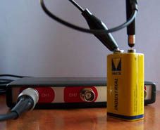
When measuring DC signals, like e.g. battery voltages, two things have to be kept in mind, to perform proper, accurate measurements.
Signal coupling
The signal coupling of a channel determines how the input signal is coupled to the input system: AC coupled or DC coupled.
AC coupling
When the input is AC coupled, the input signal will be capacitively coupled to the input system. The DC component of the signal will be blocked. This setting is particularly useful for investigating a small AC ripple on a rather large DC component.
AC coupling is indicated by an AC symbol on the  Coupling button on the channel toolbar.
DC coupling
When the input is DC coupled, the input signal will be directly coupled to the input system. All frequency components will be passed on to the input system.
DC coupling is indicated by a DC symbol on the  Coupling button on the channel toolbar
When measuring DC signals, make sure to set the signal coupling to DC. This will allow the DC component of the signal to be passed on to the input system. When AC is used, the DC component is blocked and the (much smaller) noise will only be measured, resulting in wrong measurement results.
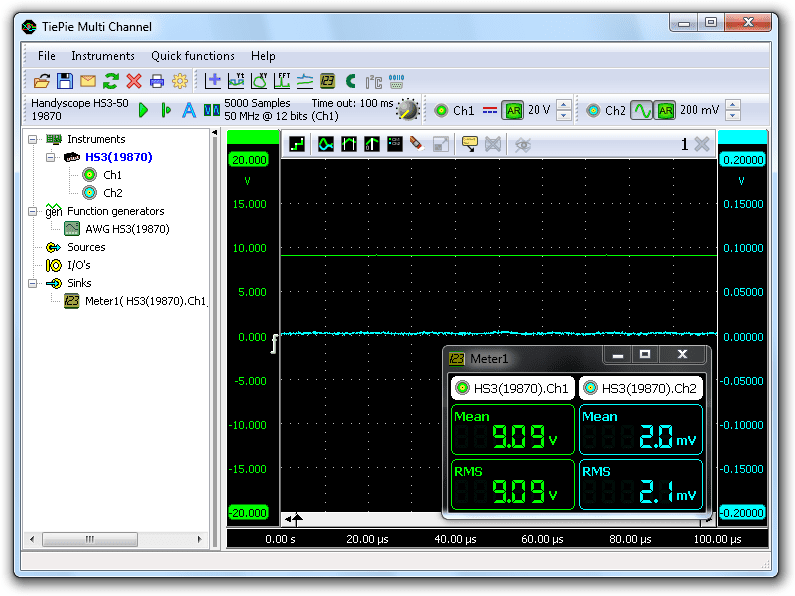
In the above measurement, Ch1 and Ch2 both measure the same DC voltage, from a battery. Ch1 uses DC coupling and Ch2 uses AC coupling.
Trigger time out
When a measurement is started, the instrument will wait until the trigger conditions are met before the post samples are measured and the measurement is finalized.
If the trigger conditions are set in such a way that the input signal(s) will never meet the trigger settings, the instrument will wait forever. When no measurement is performed, no signals will be displayed. A DC signal from e.g. a battery will be continuously having the same amplitude. When edge trigger is selected, the trigger system will wait inifinitely for an edge in the trigger signal, before the measurement is started, because the signal has no edges.
To avoid that the system will wait infinitely, a trigger time out is added to the trigger system. When after a user defined amount of time after starting the measurement still no trigger has occurred, the trigger time out will force a trigger.
When measuring DC signals without much amplitude variation, make sure to set the trigger time out value to a value unequal to infinite, e.g. 100 ms.