Contents
- 1 Introduction
- 2 Requirements
- 3 Setting up the hardware
- 4 Setting up the software
- 4.1 Input sensitivity
- 4.2 Calibrating the sensor
- 4.3 Converting the measured values
- 4.3.1 Set the gain
- 4.3.2 Set the offset
- 4.3.3 Set the unit of measure
- 4.3.4 Set the alias
- 4.3.5 Connect the I/O
- 4.3.6 Set the output range
- 4.4 Measuring in m/s2
- 5 Ready to measure
- 6 Measuring speed
- 7 Measuring displacement
Introduction
Acceleration measurement is used in many branches of the industry, to check and avoid vibration in mechanical systems or to track moving objects.
To measure acceleration, several different sensors are available, which convert acceleration into an electrical signal, which can be measured with a standard measuring instrument.
Requirements
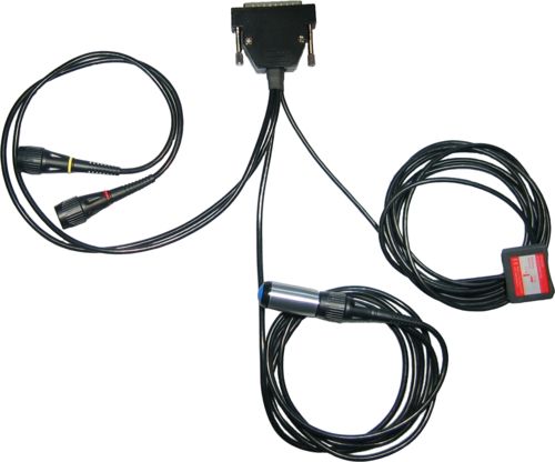
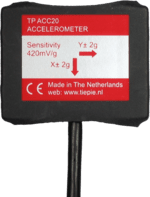
The TiePie engineering Accelerometer TP-ACC20 is the ideal sensor for measuring static and dynamic accelerations in two directions. By means of two BNC connectors, the Accelerometer TP-ACC20 is connected to two inputs of the measuring instrument. Power is supplied to the Accelerometer TP-ACC20 through the D-Sub connector on the back of the measuring instrument. The Accelerometer TP-ACC20 - 09 features a 9 pin D-Sub connector to connect to the instrument. The Accelerometer TP-ACC20 - 25 features a 25 pin D-Sub connector to connect to the instrument. No additional cables or power supplies are required. The Accelerometer TP-ACC20 is designed to work with the following instruments:
| Accelerometer TP-ACC20 - 09 | Accelerometer TP-ACC20 - 25 |
|---|---|
|
WiFiScope WS6 DIFF WiFiScope WS6 WiFiScope WS5 Handyscope HS6 DIFF Handyscope HS5 |
WiFiScope WS4 DIFF Handyscope HS4 DIFF Handyscope HS4 Handyscope HS3 |
|
Automotive Test Scope ATS610004DW-XMSG Automotive Test Scope ATS605004DW-XMS Automotive Test Scope ATS610004D-XMSG Automotive Test Scope ATS605004D-XMS |
Automotive Test Scope ATS5004DW Automotive Test Scope ATS5004D |
This measuring example describes an acceleration measurement performed with the Accelerometer TP-ACC20, connected to a Handyscope HS4, using the Multi Channel oscilloscope software.
Setting up the hardware
First the D-Sub connector of the Accelerometer TP-ACC20 must be connected to the extension connector on the rear panel of the Handyscope HS4. This connector supplies the required power to the Accelerometer TP-ACC20.
The next step is connecting the signal cables to the inputs of the Handyscope HS4. The two signal cables are color coded, red for the acceleration signal in X direction, yellow for the acceleration signal in Y direction. In this example, the X signal is connected to Ch1, the Y signal to Ch2.
The Accelerometer TP-ACC20 can measure accelerations in two axes. For initial calibration, the Accelerometer TP-ACC20 should be placed so that both axes are in their idle state, parallel to the earth's surface. To achieve this, place the Accelerometer TP-ACC20 on a stable, not moving surface, with the label facing up.
Setting up the software
Input sensitivity
When idle and not moving, the Accelerometer TP-ACC20 has an output offset of approximately
1.4 V.
The Accelerometer TP-ACC20 has a typical output sensitivity of 420 mV per g
acceleration and a range of approximately -2 to +2 g.
This would give a maximum output voltage of almost 2.5 V.
This makes the 4 V range the most suitable input range for a channel.
Auto ranging is not convenient when doing acceleration measurements, therefore,
switch Auto ranging off, by clicking the  Auto ranging button on the channel toolbar
of the required channels.
Auto ranging button on the channel toolbar
of the required channels.
Calibrating the sensor
When idle and not moving, the Accelerometer TP-ACC20 has an output offset of approximately 1.4 V and an output sensitivity of 420 mV per g.
To calibrate the sensor, first place it on a stable, not moving surface, with the label facing up. Use the cursors in the software to measure the offset voltage on both channels.
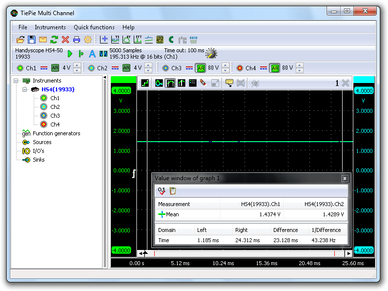
In the screen shot above, the offset value for Ch1 is 1.4374 V and for Ch2 is 1.4289 V.
To calibrate the sensitivity, a known acceleration has to be applied and the output voltage has to be measured. Since the Accelerometer TP-ACC20 is capable to measure static acceleration, it can measure the earth's gravity, being 1 g.
To measure the earth's gravity, place the sensor on a stable, not moving surface, with the X axis parallel to the earth surface and the Y axis pointing up or downwards, perpendicular to the earth surface. The Y axis, is now experiencing +1 g, measure the voltage on channel 2.
Then rotate the sensor 180 degrees around the X axis, the Y axis is now pointing down, experiencing -1 g. Measure the voltage on Ch2 again.
Repeat this with the Y axis parallel to the earth surface and the X axis pointing up and down and measure the voltages on Ch1.
As a result, six voltages are measured: +1 g, 0 g and -1 g on both axes:
| -1 g | 0 g | +1 g | |
|---|---|---|---|
| X axis | 1.0259 V | 1.4374 V | 1.8448 V |
| Y axis | 1.0382 V | 1.4289 V | 1.8598 V |
The sensitivity for a channel can now be determined with:
sensitivity = (V+1g - V-1g) / 2
This results in the following sensitivities: X axis = 409.45 mV/g and Y axis = 410.80 mV/g
Converting the measured values
When displaying the signal of the Accelerometer TP-ACC20 directly, the oscilloscope will display volts, not in g's or in m/s2. To display the measured accelerations with unit g or m/s2, the measured values need to be converted.
To convert the measured values, a Gain/Offset I/O is used for each channel of the Accelerometer TP-ACC20. Create them by right-clicking on I/Os in the object screen and selecting Gain/Offset.
Since all operations for both channels are similar, this example will only describe the settings for the X axis, Ch1.
Set the gain
As determined before, the Accelerometer TP-ACC20 has an X axis sensitivity of 409.45 mV/g. To display the measured values directly in g's, they have to be multiplied by 1 / 0.40945 = 2.4423. Right-click the X axis Gain/Offset I/O and select . There is no need to calculate the proper value for the gain, the Gain/Offset I/O can do this by itself, so simply enter "1 / 0.40945", "1/409.45m" or "1/409m45".

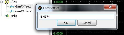
Set the offset
To compensate for the offset of the Accelerometer TP-ACC20, right-click the Gain/Offset I/O and select . Then enter the measured offset value, multiplied by -1. In this example, the offset for the X axis is 1.4374 V, so a value of "-1.4374" has to be entered.
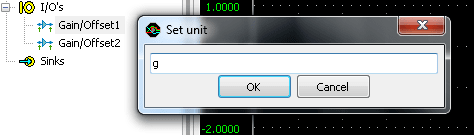
Set the unit of measure
Since gravity can be represented as g, the unit of measure should be given as g as well. To change this, right-click the Gain/Offset I/O and select Set Unit... and enter "g".
Set the alias
To simplify recognition of the various signals that can be displayed, it is possible to assign a name (alias) to an I/O. Right-click the Gain/Offset I/O and select Set alias... and enter "X axis".

Connect the I/O
The X axis Gain/Offset I/O is now ready for use. Drag input channel Ch1 of the instrument on the X axis Gain/Offset I/O and then drag the Gain/Offset I/O in the graph. The new graph shows the acceleration in one axis, directly in g. The corresponding live channel of the instrument can now be deleted from the graph. For more information, see "Creating and connecting objects".
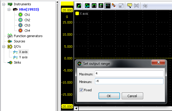
Set the output range
To customize the visible range of the converted accelerometer data, right-click the Gain/Offset I/O and select Set output range... to set the visible range to e.g. +4 to -4 g.
Measuring in m/s2
The software is currently setup to display the measured accelerations in g. To display the measured accelerations in m/s2, a few adjustments have to be made in the settings of the Gain/Offset I/O.
The gain has to be set differently. Assuming that 1 g equals 9.81 m/s², the gain of the X axis Gain/Offset I/O has to be set to "9.81 * (1 / 0.40945)" in the above example. The units have to be changed from "g" to "m/s²".
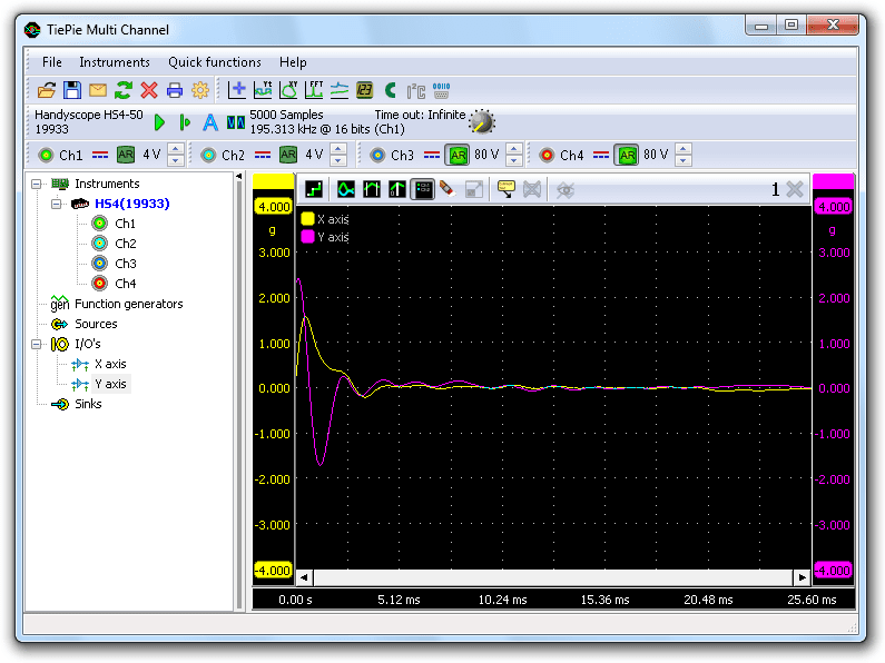
Ready to measure
The TiePie engineering Multi Channel oscilloscope software is now ready to measure both the tilt and the accelerations that the Accelerometer is experiencing.
The measurement shown below, was made with an Accelerometer TP-ACC20, sliding on a horizontal surface and bouncing against an obstacle. The measurement data and settings are saved in a Multi Channel oscilloscope software TPS file:
This setfile can be opened with the Multi Channel oscilloscope software.
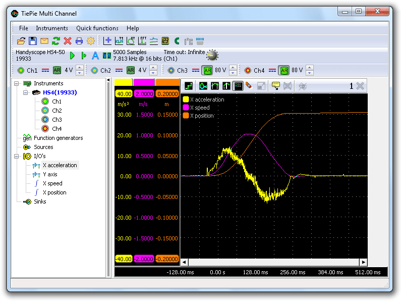
Measuring speed
When the acceleration of an object is known, as well as the initial speed of the object, it is very easy to determine the speed of the object, using an accelerometer. All one has to do is measure the acceleration in m/s2 and integrate the measured data to get the speed in m/s. The Multi Channel oscilloscope software has an Integrate I/O that can be used for this task.
Create an Integrate I/O by right-clicking I/Os in the object screen and select Integrate. The alias of the Integrate I/O can be set to e.g. "X speed". Set the unit to "m/s". Then drag the X axis Gain/Offset I/O onto the Integrate I/O and drag the Integrate I/O on the graph.
The graph now displays the speed of the object, in m/s.
Measuring displacement
When the speed of an object is known, the displacement of that object can be determined very easy by integrating the speed.
Create another Integrate I/O, name it "X position" and set the unit to "m". Now drag the X speed Integrate I/O on the X position Integrate I/O and drag the X position Integrate I/O on the graph.
The graph now displays the relative position, or displacement, of the object, in m. The image below shows a measurement with an Accelerometer TP-ACC20, which was shifted over a table, for about 15 cm.
This measurement example can be downloaded as well: