Contents
Voltage is defined as the electrical potential difference between two points. So, when measuring a voltage, it is measured between two points.
Single-ended oscilloscope inputs
Most oscilloscopes are equipped with standard, single-ended inputs, which are referenced to ground. This means that one side of the input is always connected to ground and the other side to the point of interest in the circuit under test.
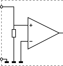
Therefore the voltage that is measured with an oscilloscope with standard, single-ended inputs is always measured between that specific point and ground.
What if the voltage you're interested in is not referenced to ground? Connecting a standard single-ended oscilloscope input to the two points would create a short circuit between one of the points and ground, possibly damaging the circuit and the oscilloscope.
A safe way would be to measure the voltage at one of the two points, in reference to ground and at the other point, in reference to ground and then calculate the voltage difference between the two points. On most oscilloscopes this can be done by connecting one of the channels to one point and another channel to the other point and then use the math function Ch1 - Ch2 in the oscilloscope to display the actual voltage difference.
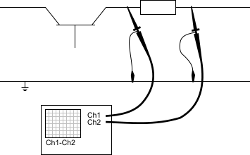
There are some disadvantages to this method:
- to measure one signal, two channels are occupied.
- by using two channels, the measurement error is increased, the errors made on each channel will be combined, resulting in a larger total measurement error.
- The Common Mode Rejection Ratio of this method is relatively low. If both points have a relative high voltage, but the voltage difference between the two points is small, the voltage difference can only be measured in a high input range, resulting in a low resolution.
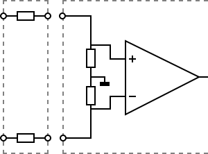
Differential oscilloscope inputs
Some oscilloscopes are equipped with a differential input. A differential input is not referenced to ground, but both sides of the input are "floating".
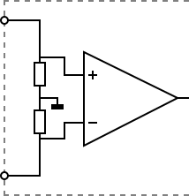
It is therefore possible to connect one side of the input to one point in the circuit and the other side of the input to the other point in the circuit and measure the voltage difference directly.
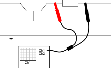
Advantages of a differential input:
- No possibility to create a short circuit to ground through the oscilloscope.
- Only one channel is used to measure the signal.
- More accurate measurement, since only one channel introduces a measurement error.
- The Common Mode Rejection Ratio of a differential input is high. If both points have a relative high voltage, but the voltage difference between the two points is small, the voltage difference can be measured in a low input range, resulting in a high resolution.
Applications
There are various applications for oscilloscopes with differential inputs.
Power systems
One application for oscilloscopes with differential inputs is measurements in (switch mode) power supplies, motor drives, frequency inverters. The high common mode voltages and low voltage differences make an oscilloscope with differential inputs the ideal measuring instrument. It also reduces the risk of creating short circuits, resulting in damaged circuits and/or measuring instruments.
Communication buses
Oscilloscopes with differential inputs can also be used very well when measuring at (high speed) digital communication buses like e.g. USB and CAN.
To improve signal integrity, such buses use two differential signal lines and a common ground line. The two signal lines transport the same signal, with the difference that they are each others inverse. This reduces the effect of external influences, since most external disturbances are additive and cause the same offset error in both signal lines. The voltage difference will remain the same, so the actual signal is not affected. To measure the actual signal, a differential input is required.
Audio systems
Another application for oscilloscopes with differential inputs is measuring in professional audio systems. Just as for the digital buses described above, also in professional audio systems two signal lines and a ground line are used to improve the signal integrity (here called "balanced").
Products
TiePie engineering has a number of products for measuring with differential inputs.
WiFiScope WS6 DIFF
The WiFiScope WS6 DIFF high resolution oscilloscope is a portable, battery powered WiFi oscilloscope with four differential high accuracy inputs that will measure with resolutions of 8, 12, 14 and 16 bit.
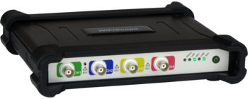
The WiFiScope WS6 DIFF high resolution oscilloscope combines a high accuracy input with a resolution of up to 16 bit resolution with a sample frequency up to 1 GSa/s and a record length up to 256 MSamples. Additionally, it features differential / single-ended switchable inputs with SafeGround, SureConnect connection test and CMI.
For more information and specifications, refer to the page about the WiFiScope WS6 DIFF.
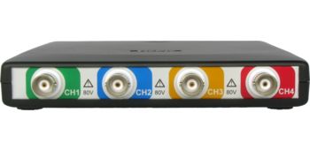
WiFiScope WS4 DIFF
The WiFiScope WS4 DIFF is a powerful computer controlled battery powered WiFi oscilloscope that features
four built-in differential input channels.

The WiFi / LAN / USB connected WiFiScope WS4 DIFF features a user selectable 12 bit, 14 bit or 16 bit resolution, 200 mV to 80 V full scale input range, 128 Ksamples record length per channel and a sampling frequency up to 50 MHz on all four channels simultaneously.
For more information and specifications, refer to the page about the WiFiScope WS4 DIFF.
Handyscope HS6 DIFF
The Handyscope HS6 DIFF high resolution oscilloscope is a portable USB oscilloscope with four differential high accuracy inputs that will measure with resolutions of 8, 12, 14 and 16 bit.
The Handyscope HS6 DIFF high resolution oscilloscope combines a high accuracy input with a resolution of up to 16 bit resolution with a sample frequency up to 1 GS/s and a record length up to 256 MSamples. Additionally, it features SafeGround, SureConnect connection test and CMI.
For more information and specifications, refer to the page about the Handyscope HS6 DIFF.
Handyscope HS4 DIFF
The Handyscope HS4 DIFF is a powerful computer controlled measuring instrument that features four built-in differential input channels.
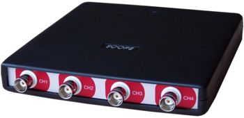
The USB connected Handyscope HS4 DIFF features a user selectable 12 bit, 14 bit or 16 bit resolution, 200 mV to 80 V full scale input range, 128 Ksamples record length per channel and a sampling frequency up to 50 MHz on all four channels simultaneously.
For more information and specifications, refer to the page about the Handyscope HS4 DIFF.
Handyprobe HP3
The Handyprobe HP3 high voltage oscilloscope is a portable USB oscilloscope with a full differential high
voltage input that will measure voltages up to 800 V DC / 566 V RMS (CAT II).
The Handyprobe HP3 high voltage oscilloscope combines a high voltage input with 10 bit resolution, 100 MSamples/second and 1 MSamples record length.
For more information and specifications, refer to the page about the Handyprobe HP3.
Handyscope TP450
The Handyscope TP450 high voltage oscilloscope is a portable USB oscilloscope with a galvanically isolated full differential high voltage input that will measure voltages up to 450 V DC / 320 V RMS (CAT II).
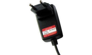
The Handyscope TP450 high voltage oscilloscope combines a high voltage input with 16 bit resolution, 250 MSamples/second and 1 MSamples record length.
For more information and specifications, refer to the page about the Handyscope TP450.
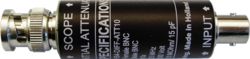
Differential attenuators
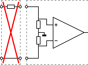
To increase the input range of a differential input, a special differential attenuator is required. For a differential input, both sides of the input need to be attenuated.
Standard oscilloscope probes and attenuators only attenuate one side of the signal path. These are not suitable to be used with a differential input. Using these on a differential input will have a negative effect on the CMRR and will introduce measurement errors.
To increase the input range of the WiFiScope WS6 DIFF, WiFiScope WS4 DIFF, Handyscope HS6 DIFF and Handyscope HS4 DIFF, they come with four differential 1:10 attenuators, the Differential attenuator TP-DA10. These differential attenuators are specially designed to be used with the Handyscope HS6 DIFF and Handyscope HS4 DIFF.
To increase the input range of the WiFiScope WS6 DIFF and Handyscope HS6 DIFF even more, up to 1000 V, the Differential attenuator TP-DA25 can be used. This X25 differential attenuator is specially designed to be used with the WiFiScope WS6 DIFF and Handyscope HS6 DIFF.
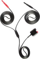
Differential measurement cables
All differential scopes come with special differential measure leads, one for each input. These differential measure leads are essential for performing differential measurements. Several different models are available, for specific instruments.
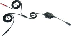
Measure lead TP-C812B
- 2 m long
- for WiFiScope WS6 DIFF, WiFiScope WS4 DIFF, Handyscope HS6 DIFF, Handyscope HS4 DIFF
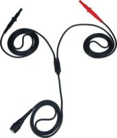
Measure lead TP-C1812B
- 3 m long
- for WiFiScope WS6 DIFF, WiFiScope WS4 DIFF, Handyscope HS6 DIFF, Handyscope HS4 DIFF
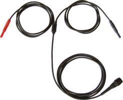
Measure lead TP-C812A
- 2 m long
- for Handyprobe HP3
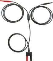
Measure lead TP-C812C
- 2 m long
- for Handyscope TP450
These cables ensure low noise measurments and a good CMRR.
Using standard BNC coax cables on a scope with differential inputs will not work. The shielding of the cable will not be connected to ground but to one side of the input. As a result, the noise from the environment will not be shielded but will be picked up and measured and shown on the signal. Only when the scope is equipped with option SafeGround, these standard cables can be used, the input then must be switched to single-ended.
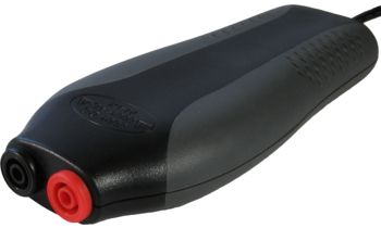
Differential probe SI-9002
To provide an existing oscilloscope with one or more differential inputs, the Differential probe SI-9002 is the ideal solution.
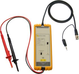
This Differential Probe provides any general oscilloscope with a high voltage differential input. Both the positive and negative sides of the balanced input possess high voltage differential input up to 700 V, and its sensitivity can extend down to 100 mV.
For more information and specifications, refer to the page about the Differential probe SI-9002