The WiFiScope WS5, Handyscope HS5 and Handyscope HS3 Arbitrary Waveform Generators can be used to generate standard as well as arbitrary signals. An arbitrary signal can be any previously measured signal or software generated data.
Contents
Control window
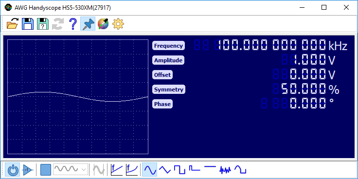
The WiFiScope WS5, Handyscope HS5 and Handyscope HS3 Arbitrary Waveform Generators can be controlled with the Arbitrary waveform generator control window, which is shown in figure 1.
The Arbitrary waveform generator control window is opened by clicking the Function Generator button
 on the main toolbar in
the application, or by double clicking the function generator in the Object screen.
on the main toolbar in
the application, or by double clicking the function generator in the Object screen.
The Arbitrary waveform generator control window contains toolbars for easy access to frequently used functions, a display to show the generated signal and control groups for signal properties. The toolbars and control groups are described below.
Toolbars
The Arbitrary waveform generator control window has two fully configurable toolbars. The toolbars can be populated with buttons for easy access to frequently used functions and signal settings:
| Icon | Action | Short description | Hotkey |
|---|---|---|---|
 |
Open | Open settings and/or arbitrary data | Ctrl + O |
 |
Save | Save settings and/or arbitrary data | Ctrl + S |
 |
Save as | Save settings and/or arbitrary data in a new file | |
 |
Reload | Reload previously opened or saved settings and/or arbitrary data | |
 |
Help | Display help about the Arbitrary waveform generator | F1 |

|
Always on top | Keep the Arbitrary waveform generator window on top of other windows | |
 |
Color scheme | Select a color scheme for the Arbitrary waveform generator control window | |
 |
Settings | Display settings to configure the Arbitrary waveform generator control window | |
 |
Output on | Switch the Arbitrary waveform generator output on or off | F2 |
 |
Output invert | Switch the Arbitrary waveform generator output invert on or off | Ctrl + F2 |


|
Start / Stop | Start / stop signal generation | spacebar |
 |
Generator mode | Select the Generator mode | |


|
Frequency mode | Select the Frequency mode | |


|
Sweep | Generate a sweep signal | |
 |
Sine | Generate a sine wave | F3 |
 |
Triangle | Generate a triangular wave | F4 |
 |
Square | Generate a square wave | F5 |
 |
Pulse | Generate a pulse signal | F9 |
 |
DC | Generate a DC level | F6 |
 |
Noise | Generate noise | F7 |
 |
Arbitrary | Generate an arbitrary signal | F8 |
Signal properties
Depending on the selected signal type and generator mode, various signal properties like frequency or amplitude can be set. To adjust a signal property, the label with the name of the property can be clicked. This opens a dialog in which the requested value can be entered. This dialog accepts prefixes like u, m, k, M, etc.
Properties can also be adjusted by clicking the digits or scrolling the mouse wheel when the mouse pointer is over a specific digit. Clicking the upper half of a digit will increase the value of that digit, while clicking the lower half of a digit decreases it. Digits that are currently off, can be enabled by clicking their upper half.

Output invert
The output invert option is used to invert the generated signal pattern. The signal is inverted around the selected offset level. Use it e.g. to create pulse signals with a negative pulse.
Generator mode
The following generator modes are supported:
| Icon | Mode | Description |
|---|---|---|
 |
Continuous | When the start button is pressed, the signal generation is started and continues until stopped by the user. |
 |
Burst | When the start button is pressed, the signal generation is started. It stops automatically after 'burst count' periods. The output then goes to the selected offset level. |
 |
Sample count | The signal pattern buffer is divided in a number of segments with a specified length in samples. When the generator is started, each time external trigger input 2 becomes active, the generator generates the next segment, after which the generator automatically stops and the output will go to the selected Offset. When all sgements have been generated, the generator will start on the first segment again, on the next activation of external trigger input 2. |

|
Sample count output | The signal pattern buffer is divided in a number of segments with a specified length in samples. When the generator is started, each time external trigger input 2 becomes active, the generator generates the next segment, after which the generator automatically stops and the output will remain at the level of the last generated sample. When all sements have been generated, the generator will start on the first segment again, on the next activation of external trigger input 2. |
 |
Gated periods | After the start button is pressed, signal generation is started at a new period, when external trigger input 2 becomes active. When external trigger input 2 becomes inactive again, the current period is finalized, signal generation stops and the output goes to the selected offset level. |
 |
Gated | When the start button is pressed, signal generation is started, but the output remains at the selected offset level until external trigger input 2 becomes active. When external trigger input 2 becomes inactive again, the output goes to the selected offset level again. |

|
Gated period start | After the start button is pressed, signal generation is started at a new period, when external trigger input 2 becomes active. When external trigger input 2 becomes inactive again, signal generation stops and the output goes to the selected offset level. |

|
Gated period finish | When the start button is pressed, signal generation is started, but the output remains at the selected offset level until external trigger input 2 becomes active. When external trigger input 2 becomes inactive again, the current period is finalized and the output goes to the selected offset level. |
 |
Gated run | After the start button is pressed, signal generation is started at a new period, when external trigger input 2 becomes active. When external trigger input 2 becomes inactive again, signal generation is paused and the output goes to the selected offset level. |

|
Gated run output | After the start button is pressed, signal generation is started at a new period, when external trigger input 2 becomes active. When external trigger input 2 becomes inactive again, signal generation is paused and the output remains at the last generated signal level. |
Note that the EXT2 input is active by default, unless pulled down.
Generator mode can only be set when the generator is stopped.
Frequency mode
When an arbitrary signal is selected, the frequency mode of the Arbitrary waveform generator can be set. The following frequency modes are supported:
| Icon | Mode | Description |
|---|---|---|
|
|
Signal frequency | The frequency controls set the frequency at which the displayed signal will be repeated. |
|
|
Sample frequency | The frequency controls set the sample frequency at which the individual samples of the displayed signal will be generated. |
With signal types sine, triangle, square and DC, the frequency mode is fixed to signal frequency. With signal type noise the frequency mode is fixed to sample frequency.
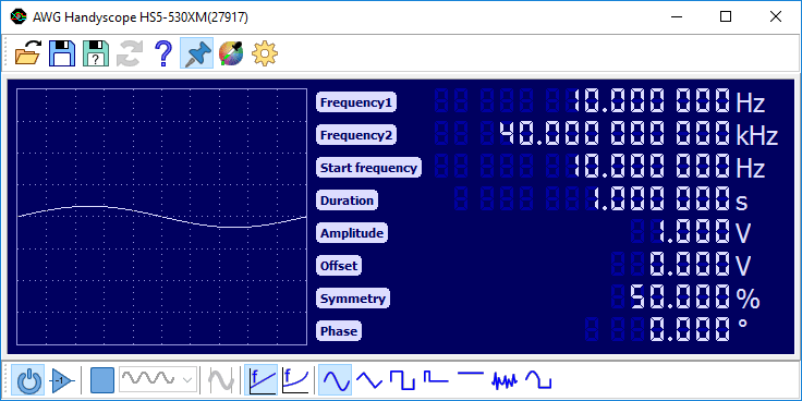
Sweep
The sweep function enables a linear or logarithmic continuous sweep with the selected signal type (sine, triangle or square). The sweep runs from Frequency1 to Frequency2, where Frequency1 is allowed to be higher than Frequency2. Optionally, the sweep can start at a different frequency than Frequency1 by setting the Start Frequency to a value between the two sweep frequencies. Duration determines the sweep duration.

The accuracy and the maximum duration of the sweep are determined by sweep settings in the settings dialog. The minimum and maximum number of samples that are used for one period of the signal can be set, as well as the maximum amount of samples for the complete sweep. Higher values will give a more accurate sweep and a longer maximum duration, but changes to sweep properties will take a bit longer to take effect.
Sweep is only available on WiFiScope WS5 and Handyscope HS5 models with extended memory option XM.
Setfiles
All settings and arbitrary data of the Arbitrary waveform generator can be saved in setfiles with the "Save" and "Save as" buttons on the toolbar or with hotkey Ctrl + S.
Setfiles can be loaded with the "Load" or "Reload" toolbar button, with hotkey Ctrl + O or by dragging a setfile onto the Arbitrary waveform generator control window.
Arbitrary data
Besides some standard signals, the Arbitrary Waveform Generator can output arbitrary data. There are different ways of loading such data into the generator. Data can be loaded directly from an open source in the software, or from a file.
Loading arbitrary data from an open source
Data of every source in the Multi Channel oscilloscope software can be loaded directly into an Arbitrary waveform generator. This means that measured data, but also processed or generated data can be put into the Arbitrary waveform generator. There are two ways to do this. One way is to drag the source onto the Arbitrary waveform generator in the object screen. The other way to get the data of a source is to drag the source onto a Arbitrary waveform generator control window.
Loading arbitrary data from a file
Besides loading data from a source, it can also be loaded from a file. Currently, loading data from TiePie engineering TPS files, TiePie engineering WinSoft DAT files, Wave audio files and from specific ASCII CSV files is supported. (WinSoft is old Tiepie engineering scope software)
From a TiePie engineering TPS file, data can be read from each Arbitrary waveform generator or Source chunk in the file.
From a TiePie engineering WinSoft DAT file, data will be read from the first channel in the file.
Data from Wave audio files can also be read into the Arbitrary waveform generator. If more than 1 channel is available in the file, only the first channel will be read. All uncompressed Wave audio files with a resolution of 8, 16, 32 or 64 bit are supported.
You can create an ASCII CSV file to be able to load your data into the function generator's memory. This file must contain a specific header line containing [SCOPE] and next various lines with waveform pattern data. Each waveform pattern line must start with 2 commas and then the sample value, its decimal separator must be a dot. The file name must have .DAT as extension.
The loaded pattern will be normalized. The highest absolute value in the pattern will be set to the selected amplitude. A value 0 will be equal to the selected offset value. All other values will be recalculated accordingly.
An example:
[SCOPE]
,,0
,,1
,,2.5
,,-4
This file contains 4 lines of waveform pattern values, but the file may contain any number of data lines.
Hotkeys
The Arbitrary waveform generator can be controlled with several hotkeys, see the hotkey page for a complete list.
Oscilloscope triggering
The Arbitrary waveform generator in the WiFiScope WS5, Handyscope HS5 and Handyscope HS3 has three trigger output signals which are internally connected to the trigger system of the oscilloscope part of the instrument. In the oscilloscope they can be used as trigger source, to provide an exact synchronization between signal generation and measuring. The available trigger signals are:
-
Generator Start
This signal is generated when continuous generation or burst generation is started, either by the Start button or by an external trigger signal. -
Generator New Period
This signal is generated when the whole buffer of the Arbitrary waveform generator has been processed and the Arbitrary waveform generator starts at the beginning of the buffer again. -
Generator Stop
This signal is generated when continuous generation of burst generation is stopped by the the Stop button or burst generation is stopped because the required number of periods has been generated.