
The CAN decoder I/O has auto level detection. The decoded fields can be shown in a table sink or passed on a to a Value extractor I/O.
When the CAN data contains J1939 messages, these are shown as well. They can be additionally extracted using the J1939 decoder I/O or the Value extractor I/O.
When the CAN data contains messages that are compatible with CANopen, exta CANopen related fields are shown as well. They can be additionally extracted using the Value extractor I/O.
The following fields are extracted from the CAN data by the decoder:
| Protocol | Field name | Purpose | Default shown |
|---|---|---|---|
| CAN | ID | (Unique) identifier for the data | |
| RTR | Remote transmission request: if 1, remote data is requested | ||
| IDE | Identifier extension bit: if 1, the ID consists of 29 instead of 11 bits | ||
| R1 | Reserved bit, only in extended format | ||
| R0 | Reserved bit (it must be set to dominant (0), but accepted as either dominant or recessive) | ||
| DLC | Data length code: number of data bytes (0-8 bytes) | ||
| Data | Transmitted data (length dictated by DLC field) | ||
| CRC | Cyclic redundancy check | ||
| CRC delimiter | Must be recessive (1) | ||
| Ack | Indicates whether the message was acknowledged | ||
| Flags | Indicates errors in the CAN data | ||
| J1939 | Priority | Message priority, provides 8 levels, 0 is highest, 7 is lowest | |
| PGN | Parameter Group Number | ||
| Source address | Source address | ||
| Reserved | Reserved for future use, must now be set to 0 | ||
| Data page | DP, selector for protocol data unit (PDU), currently at 0, page 1 for future purposes | ||
| PDU format | PF, 0-239 indicates destination address in PS, 240-255 indicates extension to PF | ||
| PDU specific | PS, content interpreted according to information in PDU Format | ||
| CANopen | Node ID | Identifies a device on the CANopen bus | |
| Function code | Identifies the CANopen message type | ||
| Object | CANopen communication object type |
To show or hide specific columns from the table, use the Select columns
( ) button
in the Table sink.
) button
in the Table sink.
Double clicking a row in the table will zoom the active graph in to the time frame corresponding to the table row.
The Value extractor I/O can be used to extract a specific CAN, CANopen or J1939 value from the decoded data and present that in a graph, a meter or a table.
An example of decoded CAN data is shown below.
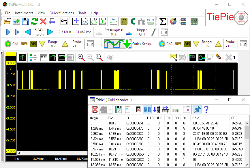
Measurement on a CAN bus in a car, with decoded CAN data.
Properties and actions
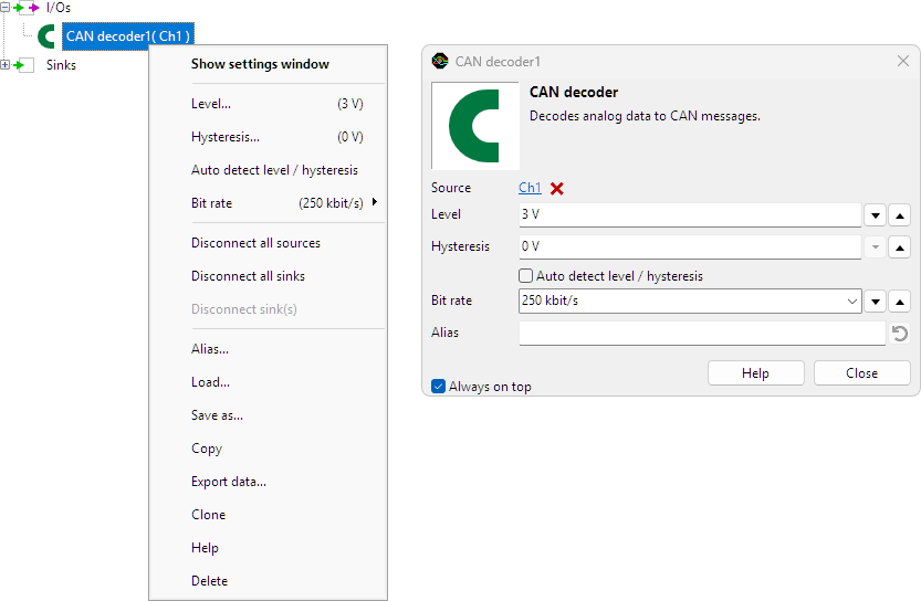
To control the behavior of the CAN decoder I/O, several properties are available.
These can be accessed through a popup menu which is shown when the I/O is right clicked in the Object screen.
The properties can also be accessed through its settings window which is shown when the I/O is double clicked in the Object screen.
To open the Object screen, click the  Show object screen button.
By default, the settings window only shows the most used settings. When Advanced is ticked, the extended window with all settings is shown. See also the program settings.
Level
In order to decode the analog signal into a digital signal, the CAN decoder I/O compares the analog input signal with a mid level: anything above that level is considered "high" and anything below that level is considered "low".
Hysteresis
To minimize the effect of noise on the signal when comparing the signal to the level, a Hysteresis can be used around that level. Anything above "level + hysteresis/2" is considered "high" and anything below "level - hysteresis/2" is considered "low".
Auto detect level and hysteresis
Enabling Auto detect level and hysteresis will let the software determine a suitable mid level and hysteresis, based on the measured signal. Each time new data is available, the suitable level and hysteresis will be determined again. In streaming mode, level and hysteresis are determined once based on the first chunk of data and remain at these values though out the whole measurement.
Auto detect level and hysteresis is default enabled.
Bit rate
For correct detection, the Bit rate property must be set to the correct value corresponding to the bus that is under measurement. It can be set to several common values, but also to a user defined value.
Common properties and actions
Related information

Add / Subtract
The Add / Subtract I/O adds or subtracts data of two or more sources.
Pulse decoder
The Pulse decoder I/O decodes the two signals from a quadrature encoder to a pulse count/position.
I2C decoder
The I2C decoder I/O decodes analog data on the SDA and SCL lines of an I2C bus to I2C data.
UART / Serial decoder
The UART / Serial decoder I/O decodes analog data on a UART, RS232, RS485, MIDI, DMX, LIN or other compatible serial bus to serial data.
J1939 decoder
The J1939 decoder I/O extracts SAE J1939 SPN values from CAN messages.
SPI decoder
The SPI decoder I/O decodes analog data on an SPI bus to SPI data.
LIN decoder
The LIN decoder I/O decodes analog data on a Local Interconnect Network bus to LIN message data.
SENT decoder
The SENT decoder I/O decodes analog signals on a SENT bus to SAE J2716 SENT messages.
DMX512 decoder
The DMX512 decoder I/O decodes analog signals on a DMX512 bus to DMX512 messages.
FlexRay decoder
The FlexRay decoder I/O decodes analog data on a bus to FlexRay message data.
Value extractor
The Value extractor I/O extracts a specific value from a decoded serial communication and makes it available for graphs, meters and tables.
Base section to index
The Base section to index I/O "fills gaps" in data with the last known value.