
In a typical crankshaft signal, gaps because of "missing" pulses are present. The signal can for example consist of three times eighteen cycles of a sine and a two cycle gap per revolution, which results in sixty cycles per revolution. The gaps are detected internally by the RPM I/O and the number of RPMs is only detected between each cycle of the sine wave.
The RPM I/O has automatic detection of the signal level.
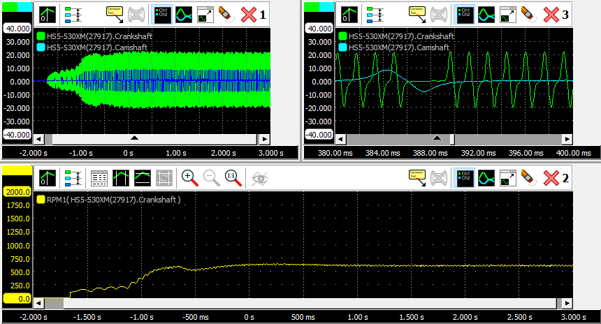
In the figure you can see a crankshaft signal of a truck during start-up (graph 1), which is converted to the engine speed with an RPM I/O (graph 2). Graph 3 is again the crankshaft signal, zoomed in at a gap in the signal.
Properties
To control the behavior of the RPM I/O, several properties are available.
These can be accessed through a popup menu which is shown when the I/O is right clicked in the Object screen.
The properties can also be accessed through its settings window which is shown when the I/O is double clicked in the Object screen.
To open the Object screen, click the  Show object screen button.
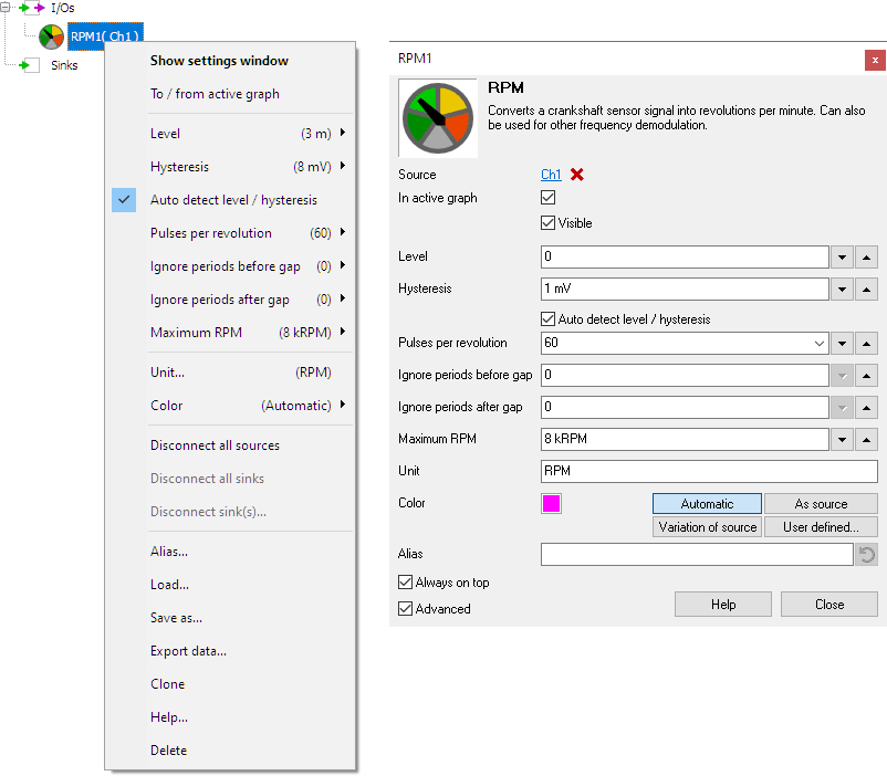
By default, the settings window only shows the most used settings. When Advanced is ticked, the extended window with all settings is shown. See also the program settings.
Level
In order to decode the analog signal into a digital signal, the RPM I/O compares the analog input signal with a mid level: anything above that level is considered "high" and anything below that level is considered "low".
Hysteresis
To minimize the effect of noise on the signal when comparing the signal to the level, a Hysteresis can be used around that level. Anything above "level + hysteresis/2" is considered "high" and anything below "level - hysteresis/2" is considered "low".
Auto detect level and hysteresis
Enabling Auto detect level and hysteresis will let the software determine a suitable mid level and hysteresis, based on the measured signal. Each time new data is available, the suitable level and hysteresis will be determined again. In streaming mode, level and hysteresis are determined once based on the first chunk of data and remain at these values though out the whole measurement.
Auto detect level and hysteresis is default enabled.
Pulses per revolution
The Pulses per revolution property must be filled with the number of periods that the crankshaft signal of the used engine produces per revolution. This number must included the "missing" pulses in the gap(s). Several commonly used values can be selected from, a user defined setting is available as well. The default setting is 60 pulses per revolution.
Ignore periods before gap
In a typical crankshaft signal, gaps because of "missing" pulses are present. In some crankshaft signals, the signal shape at the start of the gap can cause the RPM I/O to make a wrong rpm determination, resulting in a strange peak or dip in the rpm graph. The property Ignore periods before gap tells the RPM I/O to ignore periods before the gap, giving a more stable rpm determination. Several default values can be selected from, as well as a user defined setting. The default setting is 0.
Ignore periods after gap
In a typical crankshaft signal, gaps because of "missing" pulses are present. In some crankshaft signals, the signal shape at the end of the gap can cause the RPM I/O to make a wrong rpm determination, resulting in a strange peak or dip in the rpm graph. The property Ignore periods after gap tells the RPM I/O to ignore periods after the gap, giving a more stable rpm determination. Several default values can be selected from, as well as a user defined setting. The default setting is 0.
Maximum RPM
The property Maximum RPM sets the upper limit of the output range of the RPM I/O. Several default values are available, as well as a user defined setting.
Common properties and actions
Related information

Resampler
The Resampler I/O resamples the source's data to decrease or increase the sample frequency (and record length with the same ratio) of a signal.
Crankshaft angle
The Crankshaft Angle I/O converts a crankshaft position sensor signal into a crankshaft angle signal.
EV charger control pilot analyzer
The EV Charger Control Pilot Analyzer I/O decodes the Control Pilot signal and shows the maximum available charge current and the charge status.