With the Multi Channel oscilloscope software you can automatically record your measurements to disk. Different file formats can be used to store the data. This page shows how to use your TiePie engineering oscilloscope as a data logger.
Contents
Data logger applications
Several ways of logging can be used for different situations. In general, two different types of logging can be distinguished:
- Continuous
- Triggered
Continuous logging creates a continuous stream of measured values from the instrument to the computer, started and stopped by the user. All values measured between starting and stopping the measurement are displayed and stored. Continuous logging can be used in situations when the measured signal has to be monitored continuously for an unlimited long time. Examples of such measurements are temperature logging, power logging, power line voltage monitoring and current logging. Any voltage or sensor output can be measured continuously and recorded to disk. Besides logging measurements directly, it is possible to process measured data first. You can for example measure the current through, and the voltage over a load, multiply the two measurements to get the real power, and write the result to a file.
When Triggered logging, the signals are constantly monitored and when they meet a specified condition, a measurement with a predefined length is performed. This measurement is then displayed and stored to disk. After that, the system will start monitoring the input signals again, waiting for the next time the signals meet the specified condition.
It is essential to set the trigger time-out to infinite.
Triggered logging can be used in situations when the event of interest is occurring every once in a while. By adjusting the instrument trigger settings such that it will trigger only on the event, all events of interest will be measured. When logging is enabled, all these measurements will be stored. You can for example use triggered logging to detect unusual voltages on power lines. By measuring the power line voltage and triggering when the voltage is out of the normal range, unusual voltage peaks can be detected and recorded.
How to log data
You can log data in different ways. Continuous logging can be done using the Signal logging Quick Setups. These Quick Setups setup the instrument and software for a specific logging operation with just a few mouse clicks. After selecting and loading the Quick Setup, all that needs to be done is starting the measurement. The measurement will then run for an unlimited amount of time, until it is manually stopped. All measured values are stored to disk.
These Quick Setups use Data collector I/Os. These can be set to save their content to disk in a TiePie .TPO file when they are full, then clear them self and start collecting again. Read more on logging with the Data collector.
Measurements can also be stored with the AutoDisk function to the TiePie TPS file format. In TPS files the data as well as the instrument settings are stored. Below you can read more about the auto disk function.
It is also possible to automatically store data to other file formats, such as Matlab data files (.MAT), binary files (.BIN), Comma Separated Values files (.CSV) and Wave audio files (.WAV) with the DiskWriter sink. This object can store 'normal' oscilloscope measurements, as well as streaming measurements. Below you can read more about using the disk writer.
Logging with the Data collector
When performing continuous streaming measurements, Data collector I/Os can be used to collect and "glue" the streaming data and then display it and post process it.
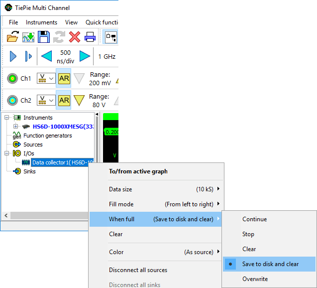
When for the Data collector property When full the option Save to disk and clear is selected, each time the Data collector is full, a .TPO file containing the Data collector is saved to disk. The Data collector is then cleared and starts collecting again. The file name for the .TPO files starts with the date and time of starting the measurement, followed by a serial number that increments each time the Data collector is full. Additionally an index file is stored keeping track of all saved .TPO files that belong to a certain measurement. The name of the index file contains the date and time of starting the measurement. The location where the files are stored can be set in the application settings. When the setup contains multiple Data collector I/Os, all saving to disk, they will all be included in the same index file. When the measurement is stopped, the final, incomplete chunck is saved as well.
When the measurement is started directly from a data logging Quick Setup and more than one chunk was saved, a dialog will appear when the measurmeent is stopped, asking to load and show all saved data.
When the measurement was setup manually without using a Quick Setup, the index file can be opened in the Multi Channel oscilloscope software, using . This will load a block of two, three or four of the saved Data collector .TPO files, depending on the data length of the saved Data collectors. The loaded Data collectors are shown together in a graph. When the original setup contained multiple Data collector I/Os, the .TPO files with matching times will be loaded and displayed together. Additionally, a special toolbar is shown that allows to navigate through the available .TPO files that belong to the specific measurement.

 Go to the first part of the measurement
 Go to the previous block of the measurement
 Go to the previous part of the measurement
 Go to the next part of the measurement
 Go to the next block of the measurement
 Go to the last part of the measurement
 Close the index file and remove all loaded Data collectors.
Clicking the indicator label on the toolbar allows to jump to a specific part of the measurement. A dialog will be shown in which the number of the required part can be entered.
It is also possible to manually load all .TPO files into the Multi Channel oscilloscope software. This will create Data collectors with the saved data. When the Data collectors are then all shown in one graph, the various parts will be displayed after each other, giving an overview of the total measurement. Note that depending on the amount of Data collectors and their data size, this can be very memory consuming.
Logging with the AutoDisk function
The AutoDisk function can be used to store all measurements of an instrument to TiePie engineering TPS files. Besides the measured data, the TPS files contain the instrument settings. Each measurement is stored in a separate file.
Logging measurements of an instrument using AutoDisk can be initiated in two ways:
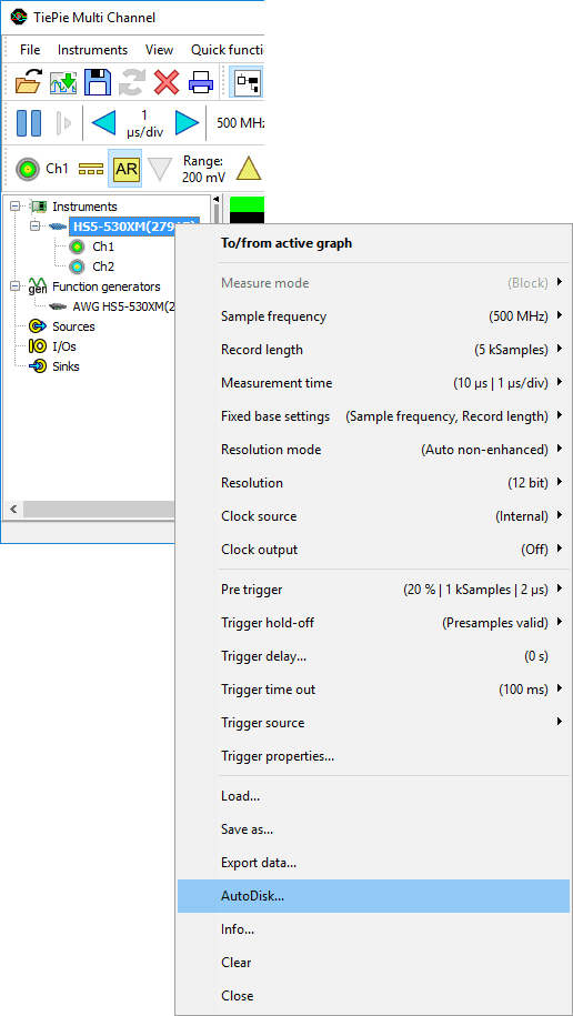
- Right-click the instrument in the object screen and choose AutoDisk... from the popup menu. An AutoDisk sink is created and the instrument is connected to it.
- Right-click Sinks in the object screen , create an AutoDisk sink and drag the instrument on it.
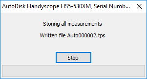
A save dialog will appear in which you can enter a file name. After choosing the file name, the auto disk function is ready to store all measurements and a window as depicted below will appear, displaying the progress. A serial number and/or time stamp is appended to the file name for each measurement. Right-click the AutoDisk sink and select Filename options to determine which are added. The serial number starts at 000000 and is incremented after each measurement. All measurements of the instrument associated with the AutoDisk function will be stored until the Stop button is pressed.
You can review the stored TPS files in different ways:
- Use File->Load... in the main menu
- Use Load... in the instrument's menu
- Drag the file from an explorer window onto the Multi Channel oscilloscope software
- Double click the file in an explorer window
Logging with the Disk Writer
With the Disk writer sink object you can store the data of any source to several file formats, unlike the auto disk function, which can only store measurements to TPS files. An advantage of this is that you can process your measurements before storing them. For example you can use a low-pass filter to filter out noise, or sum different channels to store the result. You can find more information about the DiskWriter sink on the page about the object screen .
Another advantage over the auto disk function is that the disk writer can be used to store streaming measurements. During streaming measurements, measured data is transferred to the computer in real-time, without using the instrument's memory. Because of this, it is possible to perform very long measurements and store them to disk. Files with a size up to 2 GB can be written.
Streaming measurements can be performed with all TiePie engineering USB, LAN and WiFi oscilloscopes.
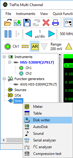
To start logging, first create a disk writer object by right clicking Sinks in the object screen and choosing the disk writer. A new disk writer object will now be created. By right-clicking the disk writer, a popup menu will show in which several settings can be changed. Entering a file name in the settings window of the writer is required.
When all settings are correct, you can connect the source(s) of which you want to store the data by dragging it/them onto the writer. If you want to store all channels of an instrument, you can drag the instrument instead of the single channels. After the objects are connected, all data will be recorded.