The Disk writer sink can be used to store measured data directly to disk.
Data from one or more sources can be stored.
Both 'normal' oscilloscope measurements and streaming measurements can be stored.
When streaming measurements are stored, the newly arriving data will be appended to the
previous data, forming one large block of data per stream.
Data can be written in several common file formats.
For more information about recording or logging data to disk, see the page about
data logging.
The Disk writer sink can store streaming data directly. Do not store streaming data that is collected in a Data collector I/O using a Disk writer. Each time the Data collector receives new data, this will be signaled to the Disk writer, which will then add the complete Data collector content to the file, not just the new data.
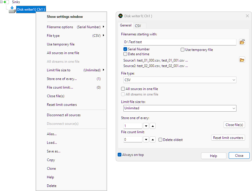
To control the behavior of the Disk writer sink, several properties are available. These can be accessed through a settings window, as shown below and through the popup menu that is shown when the Disk writer sink is right clicked in the object tree.
When the first source is connected to the writer, a settings window as depicted in the figure below will show. The settings window is also shown when clicking Show settings window in the popup menu of the Disk writer.
In most cases multiple files are used to save the data. The name of the files is a base filename with optional numbers appended. The base filename can be entered in the top edit box on the settings window of the Disk writer.
When multiple files are saved, optionally a Serial number can be added to the base filename. Serial numbers starting with 0 are used. This property is default on and can only be switched off when another file identification such as a time stamp is added.
When Date and time is checked, the date and time in millisecond precision will be added to the file name in the following format:
"YYYYMMDD_HHMMSS-MMM"
The Disk writer sink can store the data in files of common File types. The File type can be set through the settings window and through the popup menu. The following file types are available:
Matlab .mat files can contain data from multiple sources and can contain multiple streams. In Matlab .mat files all object data is stored in separate structures, each with its one time base and other information. There are three different structures that are used:
Time based signals, as well as frequency based signals (spectra) can be exported to Matlab .mat files. When a spectrum is saved, the PreSampleCount field is not stored, and the SampleFrequency field is replaced by the BinsPerHz field. The value of this field is expressed in Samples/Hz, similar to the SampleFrequency field, which has unit Samples/s. Both fields can be used to reconstruct the horizontal axis.
Information about the MAT-file format can be found at the MathWorks site.
For each selected single source or output, a src structure is written to the file. The src structure contains the following properties:
| Field name | Meaning |
|---|---|
| name | name of the source |
| DateTime | floating point number representing the time and date: 1 corresponds to 1-Jan-00001 |
| RangeMin | low value of the data range |
| RangeMax | high value of the data range |
| SampleFrequency2 | sample frequency of the data |
| PreSampleCount3 | number of presamples in Data array |
| StartValue | relative start time of the post samples |
| Unit | unit of the data |
| Data | array containing the samples |
For each selected object with multiple synchronous outputs, a msrc structure is written to the file. An instrument is an example of an object with multiple synchronous outputs. This structure looks a lot like the src structure. The difference is that some fields are now arrays instead of single values and the field srcnames is added. The msrc structure contains the following properties:
| Field name | Meaning |
|---|---|
| name | name of the object |
| srcnames | names of the outputs |
| DateTime | floating point number representing the time and date: 1 corresponds to 1-Jan-00001 |
| RangeMin | low values of the data ranges |
| RangeMax | high values of the data ranges |
| SampleFrequency2 | sample frequency of the data |
| PreSampleCount3 | number of presamples in Data array |
| StartValue | relative start time of the post samples |
| Unit | units |
| Data | 2 dimensional array containing the samples |
For each selected object with multiple asynchronous outputs, a amsrc structure is written to the file. Currently there are no objects with multiple asynchronous outputs. The msrc structure contains the following properties:
| Field name | Meaning |
|---|---|
| name | name of the object |
| DateTime | floating point number representing the time and date: 1 corresponds to 1-Jan-00001 |
| srcs | array containing a src structure for each output |
Binary files contain nothing more than raw data. No information about sample frequency, range, number of sources, number of samples etc. is included.
Data can be stored in the following Data types:
|
|
This file type supports multiple sources in one file. When multiple sources are included in one file, the data of the different sources is interleaved, starting with sample 0 of source 0, then sample 0 of source 1 etc.
There are some limitations when exporting data to this format. For time base signals:
For frequency based signals (spectra):
The binary file only contains raw data, no information about the data is saved. When saving measured data to binary files, also save the setup to a TPS file and store that together with the BIN files. That way, the structure of the BIN files (number of sources, data type) is kept with the files and they can be read properly in a later stage.
Comma Separated Values files are supported by a great number of programs. The data is stored in human readable form using ASCII characters and can be viewed with any text editor. The name of the file type is a bit misleading: mostly semicolons (;) are used as column separator instead of commas (,).
The exported CSV files contain a header with some information and a column of data for each source. Optionally a time base and/or sample number column can be written. The columns are by default separated by a semicolon (;), but another separator may be chosen as well. The default decimal separator is a point (.), but it can be changed to a comma (,).
The data values can be formatted in different ways:
The meaning of the precision and digits values are as follows:
| Number format | Precision | Digits |
|---|---|---|
| General | Number of significant digits | Minimum number of digits in exponent |
| Fixed | Number of significant digits | Number of digits after the decimal point |
| Scientific | Number of significant digits | Minimum number of digits in exponent |
There are some limitations when exporting data to this format. For time based signals:
For frequency based signals (spectra):
Normally, wave files are used only for audio data, but they can also be used to store measurement data. A disadvantage of wave files is that not all information can be stored. Information like measurement range and unit are lost. However, because there are a lot of wave file editors on the market, the wave file can be very convenient for editing measured data.
Most wave files contain one (mono) or two (stereo) data channels and mostly the data is stored with 8 or 16 bit precision. However, the wave file format can contain much more channels, and resolutions up to 64 bit can be used. Unfortunately, most programs that work with wave files do not support files with more than 2 channels and higher resolutions than 16 bit. Therefore, by default, the number of channels is limited to 2 and the resolution to 16 bit. The limits can be changed to write files with more channels or a higher resolution.
The wave file contains a field which contains the sample frequency of the file. For compatibility reasons, the value of the field is by default set to the standard sample frequency that is closest to the actual sample frequency. It can also be set to the original sample frequency or one of the other standard values. No resampling is performed, only the sample frequency field of the file is changed.
There are some limitations when exporting data to this format:
When the property All sources in one file is checked, the data of all sources connected to the Disk writer are written to one file. Otherwise, a separate file is created for each source. When All sources in one file is off, the source number XX starting from 1 is added to the file name. When the selected file type does not support multiple sources in one file, this property is ignored.
When the property All streams in one file is checked, the sequential streams are written to one file. Otherwise, a separate file is created for each stream or data block. When All streams in one file is off, the stream number YYY starting from 0 is added to the file name. When the selected file type does not support multiple streams in one file, this property is ignored.
When the option All streams in one file is on, but for some reason a new file is started, another number is appended to the base filename. The filename will then look like this:
"D:\TestA_XX.mat",
where A is the file number, starting from 1. A new file may be started for different reasons:
When performing measurements and All streams in one file is switched on, the Disk writer keeps the file on disk open. Other applications can not open or copy the file then. The Close file(s) action closes all open files of the Disk writer. External applications can now access the files. When new data arrives at the Disk writer, a new file will be created.
By default the maximum file size is limited to 4 GiB. Because most current applications have problems handling such big files, the Disk writer has an option to limit the file size to an arbitrary number of bytes. You can set a file size limit by choosing Limit file size to in the menu of the Disk writer.
On FAT32 file systems, the maximum allowed file size is 4 GiB. On NTFS file systems, the files may be as big as the disk.
By default all measurements are written to disk. It is also possible to change this behavior, such that one of every N measurements is written and the other measurements are skipped. This is done using the Store one of every... property.
To write the average of several measurements to disk, create an Average I/O and connect it to a Disk writer sink. Set the both the Averaging count and the Disk writer's Store one of every... properties to the same number. Disable the Running average setting of the Average I/O.
The Store one of every... property is available in the popup menu of the DiskWriter.
You can change the displayed name of an object by giving it an Alias. This can be handy when you are dealing with a lot of objects and have problems keeping them apart. You can for example give channel one of your instrument the alias "Battery", when it is measuring a battery voltage. To give an object an alias, use the item Alias ... in its menu. To remove an alias and revert to the original name of the object, set the alias to an empty string.
To disconnect all sources from an I/O or Sink at once, use the Disconnect all sources action.
When a new object is to be created, similar to an already existing object, with the same properties, the Clone action can be used. This will create an identical copy of the original object, with the exact same properties. Source(s) and sink(s) of the new object are not yet connected.
The Delete action deletes a source, I/O or sink. All connections of the object will be disconnected and then the object will be removed from the object tree. The source property of the objects that used this object as source will be cleared. The sink property of the objects that used this object as sink will be cleared. An axis in a graph that was connected to this object will be also deleted.
The Load action allows to load the settings and data for an object from a TPS or TPO file. This is detailed described on the page about Loading into selected objects.
The Save as action allows to save the settings and data of one or more objects to a TPO file. When multiple objects are selected, the connections between the objects are saved as well. This is detailed described on the page about Saving objects to a TPO file.