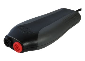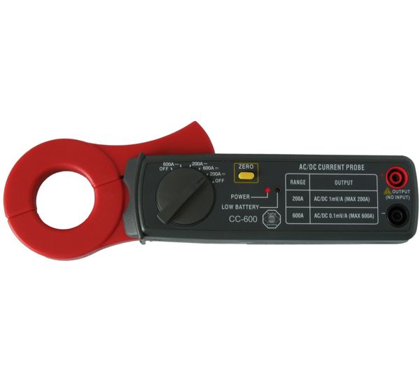
Current clamp TP-CC600
The Current clamp TP-CC600 is a current clamp that will allow your oscilloscope to measure electrical currents up to 600 Ampère AC/DC, with a frequency response up to 400 Hz. When measuring with this current clamp, there is no need to break a closed circuit or to affect the isolation.
The wide jaws allow performing measurements on thick conductors.
For measuring DC current, a simple to operate zero adjust button is available.
To connect the Current clamp TP-CC600 to your oscilloscope, a BNC to banana measure lead is required, which must be ordered separately. For oscilloscopes with differential inputs, the Measure lead TP-C812B is recommended. For oscilloscopes with single-ended inputs the Measure lead TP-BNCI-100 is recommended.
Order code: TP-CC600
EAN: 7423632935978
Price: 116.20
Category: Current Clamps
The table below shows detailed specifications of the Current clamp TP-CC600.
Electrical | |
|---|---|
| Bandwidth | DC to 400 Hz (-3dB) |
| Effective measurement range | |
| 200 A range | output 1 mV/A, 1 V = 1000 A |
| 600 A range | output 0.1 mV/A, 1 V = 10000 A |
| Accuracy | |
| DC 200 A range | ±(3% ± 0.6 A) |
| DC 600 A range | ±(3.5% ± 3 A) |
| AC 200 A range | ±(3.5% ± 0.4 A) |
| AC 600 A range | ±(4% ± 4 A) |
| Output connection | 2 shrouded 4 mm banana sockets |
Dimensions | |
| Captured conductor size | 30 mm maximum |
| Weight | 240 g |
| Height | 30 mm (1.2 inch) |
| Length | 209 mm (8.2 inch) |
| Width | 43 mm (1.7 inch) |
Power Requirements | |
| Power indicator | Red LED |
| Battery type | Standard 9 V IEC 6F22 cell |
| Low battery indication | Red LED |
Ambient | |
| Operating Temperature | 0 to 50 °C |
| Relative Humidity | 25 to 70% |
| Storage Temperature | -20 to 60 °C |
| Relative Humidity | 25 to 80% |
Certifications and Compliances | |
| CE mark compliance | Yes |
| RoHS | Yes |
The Current clamp TP-CC600 is delivered with:
| Amount | Item |
|---|---|
| 1 | Current clamp TP-CC600 |
| Description | Version | Remarks | Size | |
|---|---|---|---|---|
| Current clamp TP-CC600 user manual | 1.3 | English | 293.49 kB | download |
RELATED ARTICLES