
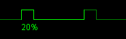
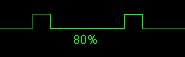
When the source data contains multiple cycles of a signal, the duty cycle will be determined for each cycle of the input signal. The output of the duty cycle I/O will then contain the progress of the duty cycle in the input data.
A typical application of the Duty cycle I/O is to analyze control signals of actuators that are duty cycle driven.
Properties
To control the behavior of the Duty cycle I/O, several properties are available.
These can be accessed through a popup menu which is shown when the I/O is right clicked in the Object Tree.
The properties can also be accessed through its settings window which is shown when the I/O is double clicked in the Object Tree.
To open the Object tree, click the  Show object tree button.
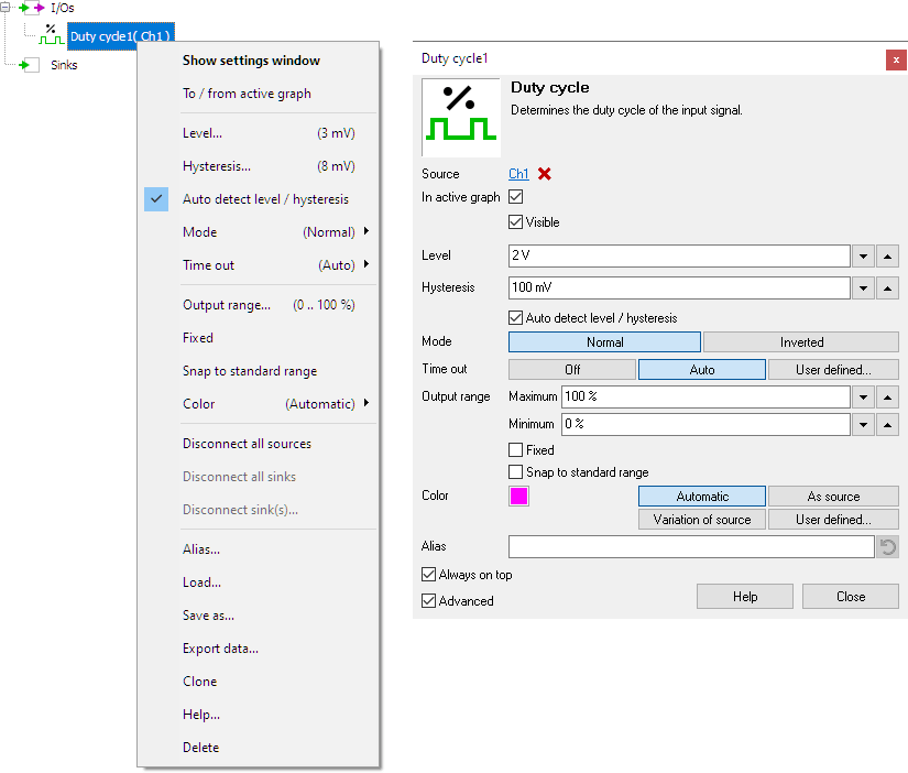
By default, the settings window only shows the most used settings. When Advanced is ticked, the extended window with all settings is shown. See also the program settings.
Level
The Duty cycle I/O locates the rising slopes in the signal, around the mid level of the signal. This mid level can be set manually using Level.
Hysteresis
To determine whether a slope is rising or falling, a hysteresis is used. This hysteresis determines how much the signal, with respect to the Level, must become larger in order to detect an edge. With a larger hysteresis, the detection is less sensitive for e.g. noise on the signal. If the hysteresis is too large, edges might be missed. This hysteresis can be set manually using Hysteresis.
Auto detect level / hysteresis
When Auto detect level / hysteresis is enabled, the I/O tries to determine the the mid level and a suitable hysteresis automatically.
Mode
The Mode property determines how the duty cycle is determined. Two types can be selected from:
-
Normal
In most applications, the active state of a signal is "high".
 The signal period of which the duty cycle is calculated starts with a rising edge.
-
Inverted
In some applications, for example in automotive applications, it is more common to consider "low" as the active state of a signal.
 The signal period of which the duty cycle is calculated starts with a falling edge.
Time out
The property Time out of the Duty Cycle I/O determines how the I/O searches for the correct cycles in the supplied signal. It has three possible settings:
- Off: The Duty Cycle I/O ignores the frequency of the duty cycle signal. If a signal is fully high or fully low for a longer period of time, this is then considered to be a cycle with a long period time, or a low frequency. The duty cycle is then calculated of the at long cycle, where it will approach either 100 % or 0 %. A duty cycle of exactly 0 % or 100 % cannot be achieved in this setting, only approached.
- Auto: The Duty Cycle I/O attempts to determine the frequency of the duty cycle signal. When a signal is fully high or fully low for a longer period of time, this is then considered to be multiple cycles, with a duty cycle of either 100 % or 0 %. When determining the signal frequency, the average of the last 10 cycles is used, to determine when a new cycle should start. When a cycle occurs that is much shorter than the average cycle length, it is considered to be a glitch and its length will not be used in the average calculation.
- User defined: The Duty Cycle I/O uses a user selected time out time to determine whether the duty cycle is 0 %, 100 % or a value in between. When, after the last cycle, the signal stays high or low longer than the selected time, this is considered to be a duty cycle of 100% or 0 % respectively. This starts a new cycle.
The default setting is Auto.
Common properties and actions
Related information

RMS
The RMS I/O determines the True Root Mean Square value of a signal.
Maximum
The Maximum I/O determines the maximum value of a signal.
Maximum - Minimum
The Maximum - Minimum I/O determines the maximum-minimum or peak to peak value of a signal.
Minimum
The Minimum I/O determines the minimum value of a signal.
Phase difference
The Phase difference I/O determines the phase difference between its two input signals.
FFT
The FFT I/O is used for spectral analysis of a signal using a Fast Fourier Transformation