Contents
Introduction
Many devices in the industrial environments are still using an RS-232 serial communication link. RS-232 uses two signal levels to distinguish between a logical "1" and a logical "0". A logical "1" is represented by -12 V and a logical "0" is represented by +12 V. RS-232 can operate on different bit rates, standard values lie between 110 bit/s and 115200 bit/s. To synchronize the sending and receiving devices, start and/or stop bits can be added to the data to transfer. RS-232 supports a simple validity check of the transmitted data, using a parity bit that can be added to the data. Two signal lines are available, TxD (Transmit Data) and RxD (Receive Data). These can be used simultaneously, which makes full-duplex communications possible.
Requirements
Measuring
To measure single RS-232 signals, a measuring instrument with at least one channel is required. To measure full-duplex signals, an instrument with at least two channels is required. The maximum frequency on the RS-232 bus depends on the bit rate that is used. The instrument must sample at at least three times the bit rate on the bus, but preferable ten times higher, on each channel. For a 110 bit/s bus that would mean a minimum sampling frequency of at least 1 kHz on both channels. RS-232 uses voltages between -12 and +12 V, so the instrument should be able to measure voltages between -12 and +12 V. Since data transfers can be long, a long record length is preferred to capture the communication.
The WiFiScope WS6 DIFF, WiFiScope WS6, WiFiScope WS5, WiFiScope WS4 DIFF, Handyscope HS6 DIFF, Handyscope HS5, Handyscope HS4 DIFF, Handyscope HS4 and the Handyscope HS3 are suitable instruments to measure RS-232 signals.
Analyzing
To examine the transferred data in the measured signals, the various pulses have to be examined, the start and stop bits have to be taken out and the parity bit too, when used. The remaining bits have to be converted into readable data.
The TiePie engineering Multi Channel oscilloscope software is capable of analyzing RS232 signals, using the UART / Serial decoder.
Generating a test signal
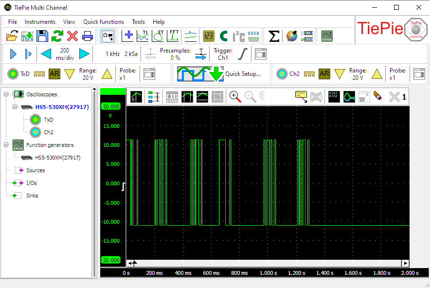
In this example, a Handyscope HS5 is used to measure serial communication from a computer running a terminal program, in which text is typed.
Open your favorite terminal program (e.g. Hyperterminal) and set it up to communicate through a serial (COM) port using the following settings:
| Setting | Value |
|---|---|
| Baud rate | 110 |
| Data bits | 8 |
| Parity | None |
| Stop bits | 1 |
| Data transport control | None |
Text typed in the terminal program should now be transmitted directly through the serial port.
Setting up the hardware
First the Handyscope HS5 is connected to the computer and the Multi Channel oscilloscope software is started.
Now connect Ch1 to the TxD line of the COM port of the computer. Connect the ground terminal of the input to CG (chassis ground) of the COM port.
COM ports use either a 9 pin or a 25 pin male D-sub connector.
| Signal | 9 pin | 25 pin |
|---|---|---|
| TxD | pin 3 | pin 2 |
| RxD | pin 2 | pin 3 |
| CG | pin 5 | pin 1 |
Setting up the software
Setting up the input channels
Since only one channel is used to measure the RS-232 signal, Ch2 of the Handyscope HS5 is removed from the screen.
We are using Ch1 to measure the Transmitted Data (TxD). To simplify recognition of the signal, it can be given a descriptive name (alias). To change the alias of a channel, right-click the channel in the object tree and select Alias... and enter the required alias. Give Ch1 the alias "TxD".
RS-232 signals lie between -12 V and +12 V, idle state = -12 V. Therefore, set the channel input coupling of the channel to "DC" and set the input sensitivity of the channel to "20 V" full scale. That way both signal levels can be measured properly.
Setting up the time base
In our example, a 110 bit/s serial communication is used. Therefore, set the time base to a sampling frequency that is ten times higher, 1 kHz. Since we will be typing text in a terminal program, we need sufficient measuring time, e.g. 2 seconds. With a sampling frequency of 1 kHz, that requires 2000 samples record length.
Setting up the trigger
In idle state, the TxD line has a logic "1", which means that the voltage on the line = -12 V. When communication starts, first a start bit, a logic "0" (+12 V) is transmitted. That means that the start of a communication sequence is a rising edge. Therefore, set the trigger type to rising edge. The trigger level and trigger hysteresis are not really important, as long as they are within the -12 to +12 V range. Set the trigger level to e.g. 50% and the hysteresis to e.g. 2.5%. To make sure that the measurement is only started when the communication begins, the trigger timeout has to be set to infinite.
Setting up the UART / Serial decoder
To analyze the RS-232 signals, the UART / serial decoder I/O is used. Create one by clicking IOs in the object tree, selecting Decode and then UART / Serial decoder.
Connect Ch1, TxD, to the serial decoder by dragging it on the serial decoder sink in the object tree.
To display the decoded UART / serial messages, a Table sink is used. Create one by clicking Sinks in the object tree and then Table. Connect the UART / serial decoder to the table sink by dragging it on the table sink in the object tree.
Port settings
Double-click the UART / Serial decoder I/O to open its settings window, to setup the port settings for the decoder.

- Level and Hysteresis
- With normal serial communication, all signal levels above Level are considered a logical "0" and all signal levels below Level - Hysteresis are considered a logical "1". The decoder can detect a Level and Hysteresis based on the measured data or the user can set voltages that will be used as level and hysteresis. Usually, Auto level and hysteresis will do, so enable Auto detect level / hysteresis.
- Invert
- With normal serial communication, a logical "0" is represented by a high voltage and a logical "1" by a low voltage. Sometimes this is inverted, a logical "1" is a high voltage and a logical "0" a low voltage. In our example, we use standard RS-232, so disable Invert.
- Baud rate
- The serial decoder can determine the baud rate of the measured signal automatically. However, it requires a minimum number of edges in the measured signal, meaning that the communication must be long enough. The decoder can also be set to a fixed baud rate. In that setting, the decoder will start analyzing the data, using the preset baud rate. In our example, a baud rate of 110 is used. Set the baud rate of the decoder to 110.
- Data bits
- Serial communication can use various numbers of data bits per transmitted "word". In our example, a 8 data bits are used. Set the number of data bits of the decoder to 8.
- Parity
- Serial communication can use different kinds of parity checks to verify the correctness of the transmitted data. In our example, no parity is used. Set the Parity of the decoder to None.
- Stop bits
- Serial communication can use different numbers of stop bits to indicate the end of a transmitted "word". In our example, 1 stop bit is used. Set the number of stop bits of the decoder to 1.
The additional settings are not relevant for decoding RS232, so can be ignored.
Ready to measure
Now everything is properly setup, type a word in the terminal program to create a serial communication. The instrument will capture this communication and the serial decoder will analyze and decode it.
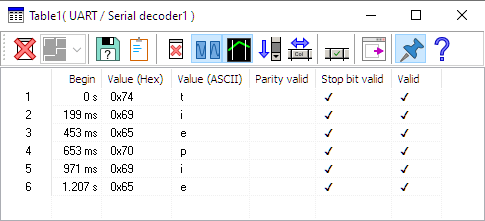
In our example, the word "tiepie" was typed and measured and converted by the serial decoder. The decoded information is shown in the table.
To clear the table for a new measurement, press the
 Clear table button.
The UART / Serial decoder can show more information in columns in the tabel that are not by default enabled.
Click the  Column select button to enable or disable columns in the table.
When a block of communication is longer than the table, it is not possible to see all text that is appended.
The table has an auto scroll function, which always makes sure the bottom lines are visible.
To toggle this function, click the  Auto scroll button.
To save the contents of the table to a file, press the
 Save as
button.
Save as
button.
To avoid the table being hidden behind other windows, press the
 Always on top button.
Cleaning dirty signals
In industrial environments, the measured signals can be very "dirty", causing the Serial decoder to have problems decoding the communication properly. Cleaning the signals may improve the ability of the Serial decoder to decode the signals properly.