
The Serial decoder sink decodes analog data on a serial bus to serial data. It can be used to monitor and analyze UART, RS232, RS485, MIDI, DMX or other compatible serial buses.
The serial decoder can monitor up to eight sources. When these sources are in sync (all sources are of one (combined) instrument), all captured data will be displayed in chronological order.
The sink uses a window for its output. The output can be saved to a text file.
Usage
Acquisition settings
For best results, use the following setups to capture the data:
| Mode | Sample frequency | Pre-trigger | Trigger timeout | Trigger type | Trigger level |
|---|---|---|---|---|---|
| Block | 3 * baudrate 1 | 1% | Infinite | Rising/Falling 2 | app. Mid level |
| Stream | 3 * baudrate 1 | - | - | - | - |
- The Serial decoder needs at least three times the baudrate to function. For proper function use always a multiple of the baudrate. (e.g. 4 or 5, don't use 3.5 or 4.5)
- If Type is set to normal use rising, if Type is set to inverted use falling.
Decoding serial buses
The serial decoder can be used to decode RS485, MIDI or DMX. See table below for settings:
| Bus | Baudrate | Databits | Parity | Stopbits | Type | Midlevel |
|---|---|---|---|---|---|---|
| DMX | 250000 | 8 | none | 2 | Normal 1 | Auto level |
| MIDI | 31250 | 8 | none | 1 | Normal | Auto level |
| RS485 | - | - | - | - | Normal 1 | Auto level |
- If measuring on the data+ of the differential bus use normal, if measuring on data- use inverted.
Serial decoder properties
To control the behavior of the Serial decoder sink, several properties are available. These can be accessed through a settings page in the output window.
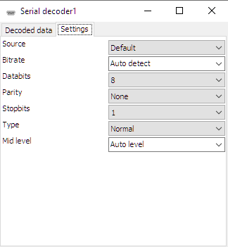
The Source selector determines which source of the Serial decoder the settings page affects. The Default selection affects the set of properties that is used when a new source is connected to the Serial decoder.
Bitrate
For correct detection, the Bitrate property must be set to the correct value corresponding to the bus that is under measurement. It can be set to several common values, but also to an Auto detect value, where the Serial decoder will determine the used bitrate. It is also possible to enter an arbitrary value in the bitrate edit field.
Databits
For correct detection, the Databits property must be set to the correct number of data bits, corresponding to the bus that is under measurement. It can be set to several common values: 5, 6, 7 or 8 bits.
Parity
For correct detection, the Parity property must be set to the correct value, corresponding to the bus that is under measurement. It can be set to several common values: None, Odd, Even, Mark or Space.
Stopbits
For correct detection, the Stopbits property must be set to the correct value, corresponding to the bus that is under measurement. It can be set to two values: 1 or 2.
Type
For correct detection, the Type property must be set to the correct value, corresponding to the bus that is under measurement. It can be set to two values:
- Normal levels above mid level are logic 0, levels below mid level are logic 1
- Inverted levels above mid level are logic 1, levels below mid level are logic 0
Mid level
For correct detection, the Mid level property must be set to the correct value, corresponding to the bus that is under measurement. The default setting is Auto level.
Output window properties and actions
To control the behavior of the Serial decoder output window, properties and actions are available. These can be accessed through a toolbar with buttons at the top of the Serial decoder output window and through a popup menu which is shown when the sink is right clicked in the Object tree.
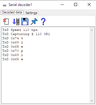
Clear
The Clear action (![]() )
clears the Serial decoder output window.
The Clear action is available as button on the toolbar.
)
clears the Serial decoder output window.
The Clear action is available as button on the toolbar.
Auto scroll to bottom
The Auto scroll to bottom property ( ) makes the Serial decoder output window scroll to the bottom of its content each time new data
has arrived, making the latest data visible.
The Auto scroll to bottom property is available as button on the toolbar.
) makes the Serial decoder output window scroll to the bottom of its content each time new data
has arrived, making the latest data visible.
The Auto scroll to bottom property is available as button on the toolbar.
Export data
The Export data action ( )
saves the content of the Serial decoder output window to a text file.
The Export data action is available as button on the toolbar.
)
saves the content of the Serial decoder output window to a text file.
The Export data action is available as button on the toolbar.
Always on top
When the Always on top property ( ) is switched on, the Serial decoder output window cannot be hidden under other windows of the
Multi Channel oscilloscope software.
The Always on top property is available as button on the toolbar and in the popup menu.
) is switched on, the Serial decoder output window cannot be hidden under other windows of the
Multi Channel oscilloscope software.
The Always on top property is available as button on the toolbar and in the popup menu.