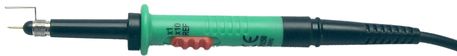
An oscilloscope probe is the connection between the input of an oscilloscope and the device under test, for measuring voltages. It is developed to pass the signal as accurate as possible, affecting the device under test as little as possible, as well as to provide an easy way to connect to the device under test.
Oscilloscope probes are available in three types:
- non-attenuating, passing the voltage at the tip directly to the oscilloscope input,
- attenuating, passing the voltage at the tip attenuated to the input of the oscilloscope,
- switchable, between attenuating and not attenuating.
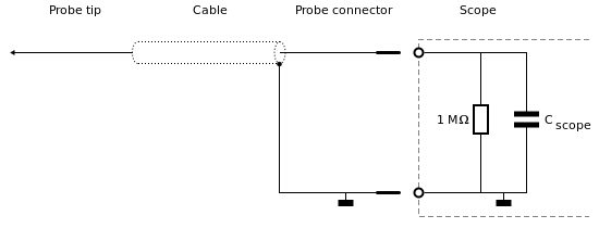
Non-attenuating oscilloscope probe
An oscilloscope input has a certain input impedance, which consists of resistance and capacitance. When using a non-attenuating oscilloscope probe or a switchable oscilloscope probe in its x1 setting, the input resistance remains unchanged, but the (parasitic) capacitance of the oscilloscope probe cable is added to the input capacitance of the oscilloscope. As a result, the bandwidth of the total system is significantly reduced.
Attenuating oscilloscope probe
An attenuating oscilloscope probe or a switchable oscilloscope probe in its attenuating setting contains an RC network that forms an attenuating network together with the input impedance of the oscilloscope. This attenuates the input signal and increases the total input impedance. As a result, a high bandwidth and a minimum load of the circuit under test is achieved.
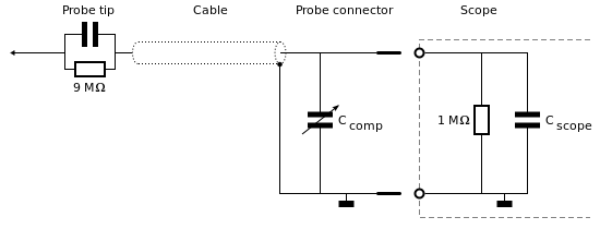
Either use a differential attenuator or switch the input to single-ended using the SafeGround option.
Compensation
In order to provide a constant attenuation over the oscilloscope probe's rated bandwidth, the RC divider must be adjusted to match the oscilloscope probe with the oscilloscope input circuit. This is called probe compensation.
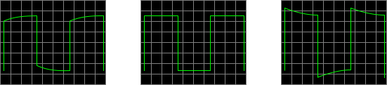
To compensate an oscilloscope probe, connect the probe tip to a 1 kHz square wave signal and connect the oscilloscope probe to an input of the oscilloscope. A switchable oscilloscope probe must be set to its attenuating setting. Use a small screw driver to adjust the set screw in the probe connector until the scope screen shows a flat top square wave. Figure 3 shows the signals of an undercompensated oscilloscope probe, a properly compensated oscilloscope probe and an overcompensated oscilloscope probe.
An improperly compensated oscilloscope probe will result in inaccurate high-frequency measurements. Therefore it is recommended to verify and correct the oscilloscope probe compensation when first connecting an oscilloscope probe to an oscilloscope, when connecting an oscilloscope probe to a different oscilloscope or when connecting an oscilloscope probe to a different input channel.
Connecting the oscilloscope probe to the circuit
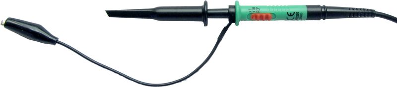
To connect the oscilloscope probe to the circuit under test, a passive oscilloscope probe is equipped with a sprung hook that allows clipping the probe tip to a test point in the circuit. To connect the probe tip ground to the ground of the circuit under test, a passive oscilloscope probe is usually equipped with a ground lead with an alligator clip that can be connected to a grounding point in the circuit. This is an acceptable and convenient solution for measuring low frequency signals.
When measuring high frequency signals or signal with high frequency components (e.g. square waves), the parasitic inductance from the long ground lead and the sprung hook combined with the input capacitance can cause overshoot and ringing in the measured signal. To avoid these problems, higher frequency oscilloscope probes are equipped with a special sprung earth tip that can be placed on the probe. It provides a very short and low inductance ground connection, causing much less overshoot and ringing on the measured signal.