
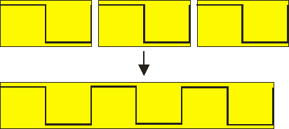
When a Data collector is used in combination with other I/Os which process the data, there are two ways to connect them to each other, each with its own advantage and disadvantage:
-
first process the data with the I/Os and then collect the data
The I/Os only have (relative) small chunks of data to process, which can be done relatively fast. The Data collector only has to collect the already processed data. The disadvantage is that the original data is not collected this way; when later turns out that the data was wrongly processed, the measurement will have to be done again. -
first collect the data and then process the data with the I/Os
The I/Os will have to process the full data size of the Data collector, even if it's only partly filled yet. This can create a very heavy load on the computer, even causing the streaming measurement to be stopped because the computer cannot keep up anymore. The advantage is that the original data is kept, making it possible to change the data processing in a later stage.
The first method is preferred in most situations. When the original data is important, it is always possible to create a second Data collector to collect the original, unprocessed data.
Logging to disk
When for the property When full the option Save to disk and clear is selected, each time the Data collector is full, a .TPO file containing the Data collector is saved to disk. The Data collector is then cleared and starts collecting again. The file name for the .TPO files starts with the date and time of starting the measurement, followed by a serial number that increments each time the Data collector is full. Additionally an index file is stored keeping track of all saved .TPO files that belong to a certain measurement. The name of the index file contains the date and time of starting the measurement. The location where the files are stored can be set in the application settings. When the setup contains multiple Data collector I/Os, all saving to disk, they will all be included in the same index file. When the measurement is stopped, the final, incomplete chuck is saved as well.
When the measurement is started directly from a data logging Quick Setup and more than one chunk was saved, a dialog will appear when the measurmeent is stopped, asking to load and show all saved data.
When the measurement was setup manually without using a Quick Setup, the index file can be opened in the Multi Channel oscilloscope software, using . This will load a block of two, three or four of the saved Data collector .TPO files, depending on the data length of the saved Data collectors. The loaded Data collectors are shown together in a graph. When the original setup contained multiple Data collector I/Os, the .TPO files with matching times will be loaded and displayed together. Additionally, a special toolbar is shown that allows to navigate through the available .TPO files that belong to the specific measurement.


Clicking the indicator label on the toolbar allows to jump to a specific part of the measurement. A dialog will be shown in which the number of the required part can be entered.
It is also possible to manually load all .TPO files into the Multi Channel oscilloscope software. This will create Data collectors with the saved data. When the Data collectors are then all shown in one graph, the various parts will be displayed after each other, giving an overview of the total measurement. Note that depending on the amount of Data collectors and their data size, this can be very memory consuming.
Properties and actions
To control the behavior of the Data collector I/O, several properties are available.
These can be accessed through a popup menu which is shown when the I/O is right clicked in the Object screen.
The properties can also be accessed through its settings window which is shown when the I/O is double clicked in the Object screen.
To open the Object screen, click the  Show object screen button.
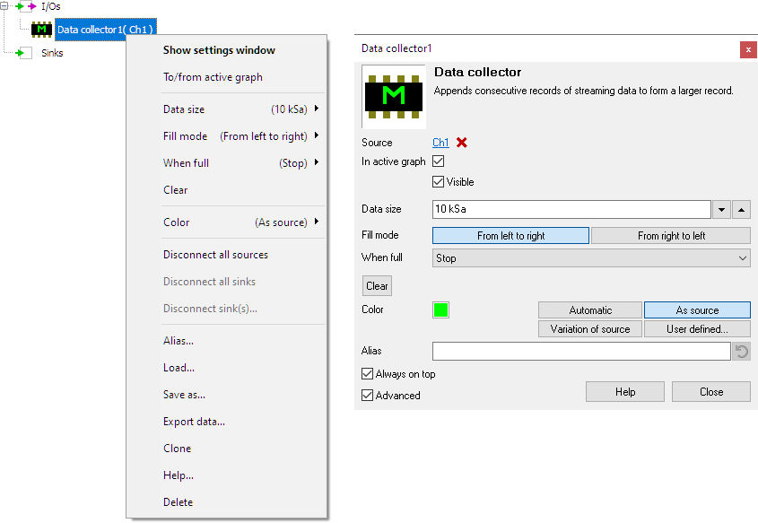
By default, the settings window only shows the most used settings. When Advanced is ticked, the extended window with all settings is shown. See also the program settings.
Data size
The Data size property sets the size (the "record length") of the Data collector. Several default values are available, as well as a user defined setting. The size of the collected data can be set to a maximum of 50 million samples (for the 64 bit version of the Multi Channel oscilloscope software, 20 million samples for the 32 bit version).
When Fill mode is set to From right to left, or When full is set to Continue, the maximum data size is 1 million samples.
Fill Mode
The Fill mode property sets how the data collector is filled with data.
- From left to right: new data is appended starting from the left.
- From right to left: existing data is shifted to left, new data is appended at the right. This option is only available when the data size is 1 million samples or smaller.
When full
The When full property determines what action the Data collector performs when the output data block is full.
- Continue: The oldest data is shifted out at the left, while new data is appended to the right. This option is only available when the data size is 1 million samples or smaller.
- Stop: Data collecting is stopped when the Data collector I/O is full. (The measurement is NOT stopped.)
- Clear: The Data collector is cleared and the filling starts over again.
- Save to disk and clear: The output data is saved to disk in a .TPO file, the data is then cleared and filling starts over again. This setting is not available when Fill mode is set to From right to left.
- Overwrite: Existing data in the Data collector is overwritten by the new data, starting at the beginning again (roll mode). This setting is not available when Fill mode is set to From right to left.
When Overwrite is selected, the old data remains on screen but is overwritten from the beginning of the Data collector. A section of a minor division wide in the signal line in front of the new data is not being drawn, resulting in a gap in the signal line, to make clear where the old data is being replaced by the new data.
When Overwrite is selected and the Data collector has been full at least once and is overwriting old data:
- The numbers along the horizontal axis in the graph(s) showing the Data collector only indicate the position in the Data collector, they no longer correspond to the actual measurement time.
- Time difference determination between a moment in the new data (left from the gap) and a moment in the old data (right from the gap) is not possible.
- The cursors only work on the new data, to the left of the gap in the signal line
Clear
The Data collector I/O can be manually cleared with the Clear action.
Common properties and actions
Related information
