
The Phase difference I/O looks for the locations of all rising slopes in both input signals. It then determines the phase differences between corresponding rising slopes. The Phase difference I/O returns one value, which is the average phase difference between the measured signals. The Phase difference is determined with respect to the first connected signal and returned in degrees or in radians.
Properties and actions
To control the behavior of the Phase difference I/O, several properties are available.
These can be accessed through a popup menu which is shown when the I/O is right clicked in the Object screen.
The properties can also be accessed through its settings window which is shown when the I/O is double clicked in the Object screen.
To open the Object screen, click the  Show object screen button.
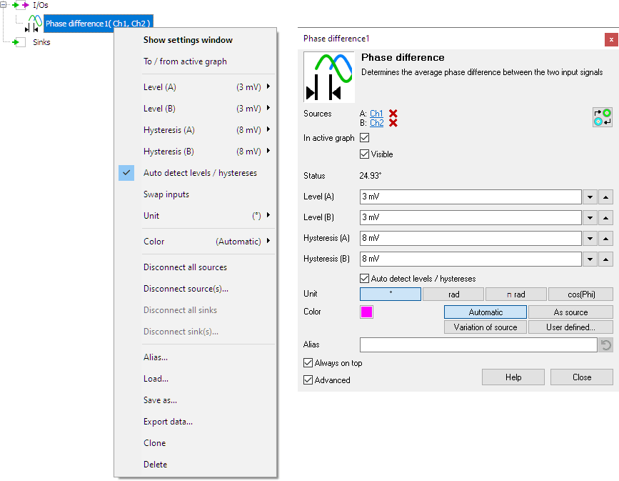
By default, the settings window only shows the most used settings. When Advanced is ticked, the extended window with all settings is shown. See also the program settings.
Swap inputs
The phase difference is determined with respect to the first connected signal (A).
If the phase needs to be determined with respsect to the other signal (B),
clicking the  Swap inputs
button will swap the two input signals and the phase will be determined with respect to the other signal.
Swap inputs
button will swap the two input signals and the phase will be determined with respect to the other signal.
Status
The Status indicates the status of the phase difference determination. When the phase difference can be determined, the status will show the determined value. When the phase difference cannot be determined, the status shows the reason why not. This happens e.g. when the frequencies of the two input signals differ too much.
Levels A and B
The Phase difference I/O locates the rising slopes in the signal, around the mid level of the signal. This mid level can be set manually for both input signals (A and B) individually using Level A and Level B.
Hystereses A and B
To determine whether a slope is rising or falling, a hysteresis is used. This hysteresis determines how much the signal, with respect to the Level, must become larger in order to detect an edge. With a larger hysteresis, the detection is less sensitive for e.g. noise on the signal. If the hysteresis is too large, edges might be missed. This hysteresis can be set manually for both input signals (A and B) individually using Hysteresis A and Hysteresis B.
Auto detect levels / hystereses
When Auto detect levels / hystereses is enabled, the I/O tries to determine the the mid levels and a suitable hysteresis for both signals automatically.
Unit
The Unit determines whether the phase difference is given in degrees (°), in radians, in π radians or as cos(phi).
Common properties and actions
Related information

Duty cycle
The Duty cycle I/O determines the duty cycle of a signal.
RMS
The RMS I/O determines the True Root Mean Square value of a signal.
Maximum
The Maximum I/O determines the maximum value of a signal.
Maximum - Minimum
The Maximum - Minimum I/O determines the maximum-minimum or peak to peak value of a signal.
Minimum
The Minimum I/O determines the minimum value of a signal.
FFT
The FFT I/O is used for spectral analysis of a signal using a Fast Fourier Transformation