
The UART / Serial decoder I/O decodes analog data on a serial bus to serial data. It can be used to monitor and analyze UART, RS232, RS485, MIDI, DMX, LIN or other compatible serial buses. The UART / Serial decoder I/O has auto level detection and auto baud rate detection. The output of the UART / Serial decoder I/O can be shown in a Table sink or passed on a to a Value extractor I/O.
The following fields are extracted from the UART / serial communication and shown as a column in the table:
| Field name | Purpose | Default shown |
|---|---|---|
| Break | Flag indicating if a Break is found | |
| Mark after break | Flag indicating if a Mark-After-Break is found | |
| Address (Hex) | The address in hexadecimal notation | |
| Address (Dec) | The address in decimal notation | |
| Value (Hex) | The value in hexadecimal notation | |
| Value (Dec) | The value in decimal notation | |
| Value (ASCII) | The value in ASCII notation | |
| Parity valid | Flag indicating if the parity is valid | |
| Stop bit valid | Flag indicating if the stop bit is valid | |
| Valid | Flag indicating if the message is valid |
To show or hide specific columns from the table, use the Select columns
( ) button
in the Table sink.
) button
in the Table sink.
Double clicking a row in the table will zoom the active graph in to the time frame corresponding to the table row.
The Value extractor I/O can be used to extract a specific value from the decoded data and present that in a graph, a meter or a table.
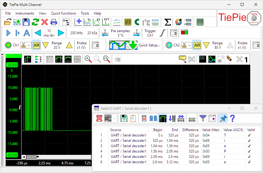
UART / Serial decoder with decoded data 'TiePie'.
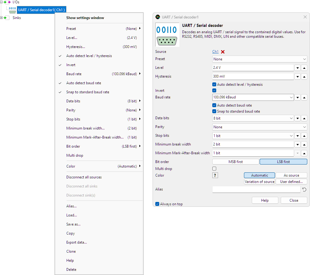
UART / Serial decoder properties
To control the behavior of the UART / Serial decoder I/O, several properties and actions are available.
These can be accessed through a popup menu which is shown when the I/O is right clicked in the Object screen.
The properties can also be accessed through its settings window which is shown when the I/O is double clicked in the Object screen.
To open the Object screen, click the  Show object screen button.
By default, the settings window only shows the most used settings. When Advanced is ticked, the extended window with all settings is shown. See also the program settings.
Preset
In order to decode the analog signal into a digital signal, the UART / Serial decoder I/O uses a level and a hysteresis to compare the analog signal to. The Preset setting offers several presets for level and hysteresis, for common serial buses that can be decoded. Setting the Preset to one of the available values will set Level and hysteresis accordingly and will disable the auto level and hysteresis detection.
Level
In order to decode the analog signal into a digital signal, the UART / Serial decoder I/O compares the analog input signal with a mid level: anything above that level is considered "high" and anything below that level is considered "low".
Hysteresis
To minimize the effect of noise on the signal when comparing the signal to the level, a Hysteresis can be used around that level. Anything above "level + hysteresis/2" is considered "high" and anything below "level - hysteresis/2" is considered "low".
Auto detect level and hysteresis
Enabling Auto detect level and hysteresis will let the software determine a suitable mid level and hysteresis, based on the measured signal. Each time new data is available, the suitable level and hysteresis will be determined again. In streaming mode, level and hysteresis are determined once based on the first chunk of data and remain at these values though out the whole measurement.
Auto detect level and hysteresis is default enabled.
Invert
For correct detection, the Invert property must be set to the correct value, corresponding to the bus that is under measurement.
- When Invert is disabled levels above signal mid level are logic 0, levels below signal mid level are logic 1
- When Invert is enabled levels above signal mid level are logic 1, levels below signal mid level are logic 0
Invert is default off.
Baud rate
For correct detection, the Baud rate property must be set to the correct value corresponding to the bus that is under measurement. It can be set to several common standard values, but it is also possible to enter an arbitrary value in the Baud rate edit field.
Auto detect baud rate
Enabling Auto detect baud rate will let the software determine the correct baud rate, based on the measured signal. Each time new data is available, the baud rate will be determined again. Auto detect baud rate is default enabled.
Snap to standard baud rate
When Auto detect baud rate is enabled, the setting Snap to standard baud rate will set the baud rate to the closest standard baud rate (from the baud rate list) if the determined value is within 1 % of this standard value. Snap to standard baud rate is default enabled.
Data bits
For correct detection, the Databits property must be set to the correct number of data bits, corresponding to the bus that is under measurement. Data bits can be set to several common values: 5, 6, 7 or 8 bits. Data bits is default set to 8 bits.
Parity
For correct detection, the Parity property must be set to the correct value, corresponding to the bus that is under measurement. It can be set to several common values: None, Odd, Even, Mark or Space. Parity is default set to None.
Stop bits
For correct detection, the Stop bits property must be set to the correct value, corresponding to the bus that is under measurement. It can be set to two values: 1 or 2. Stop bits is default set to 1.
Minimum break width
The setting Minimum break width determines the length in bits that a break must be to be considered valid. Invalid breaks are marked as invalid.
Minimum Mark-After-Break width
The setting Minimum Mark-After-Break width determines the length in bits that a mark after break must be to be considered valid. Invalid marks after break are marked as invalid.
Bit order
The bit order of transferred data on the UART / Serial bus is not defined in a standard, it depends on the implementation. The Bit order setting determines how the UART / Serial decoder will interpret the decoded bits: MSB first or LSB first. The default Bit order is LSB first.
Multi drop
Common properties and actions
Related information

Pulse decoder
The Pulse decoder I/O decodes the two signals from a quadrature encoder to a pulse count/position.
I2C decoder
The I2C decoder I/O decodes analog data on the SDA and SCL lines of an I2C bus to I2C data.
CAN decoder
The CAN decoder I/O decodes analog data to CAN data.
J1939 decoder
The J1939 decoder I/O extracts SAE J1939 SPN values from CAN messages.
SPI decoder
The SPI decoder I/O decodes analog data on an SPI bus to SPI data.
LIN decoder
The LIN decoder I/O decodes analog data on a Local Interconnect Network bus to LIN message data.
SENT decoder
The SENT decoder I/O decodes analog signals on a SENT bus to SAE J2716 SENT messages.
DMX512 decoder
The DMX512 decoder I/O decodes analog signals on a DMX512 bus to DMX512 messages.
Value extractor
The Value extractor I/O extracts a specific value from a decoded serial communication and makes it available for graphs, meters and tables.