
An encoder can also have third output, Z, which gives one pulse per revolution and can be used as zero reference signal.
Additionally, a machine in which an encoder is used, can have a Home signal, which is used by the machine controller in combination with the encoder signals.
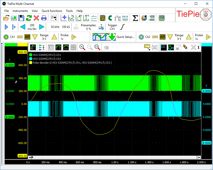
The Pulse decoder I/O has auto level detection for all signal lines. The output of the Pulse decoder can be shown in a graph and in a table
The Pulse decoder always needs two sources: the first connected source will be used as A and the second connected source will be used as B. When a third source is connected, this will be used as Z. When a fourth signal is connected, this will be used as Home.
Properties and actions
To control the behavior of the Pulse decoder I/O, several properties are available.
These can be accessed through a popup menu which is shown when the I/O is right clicked in the Object screen.
The properties can also be accessed through its settings window which is shown when the I/O is double clicked in the Object screen.
To open the Object screen, click the  Show object screen button.

By default, the settings window only shows the most used settings. When Advanced is ticked, the extended window with all settings is shown. See also the program settings.
Swap inputs
The Pulse decoder always needs two sources: the first connected source will be used as A and the second connected source will be used as B. When the sources are connected the wrong way, the Swap inputs action will correct it.
Level (A), Level (B), Level (Z) and Level (Home)
In order to decode the analog signals into a digital signal, the Pulse decoder I/O compares the analog input signals with mid levels: anything above that level is considered "high" and anything below that level is considered "low". The Level (..) properties set a mid level for the A, B, Z and Home signal individually.
Hysteresis (A), Hysteresis (B), Hysteresis (Z) and Hysteresis (Home)
To minimize the effect of noise on the signals when comparing the signals to the mid levels, a Hysteresis can be used around these levels. Anything above "level + hysteresis/2" is considered "high" and anything below "level - hysteresis/2" is considered "low". The Hysteresis (..) properties set the size of the hysteresis for the A, B, Z and Home signal individually.
Auto detect level and hysteresis
Enabling Auto detect level and hysteresis will let the software determine a suitable mid level and hysteresis, based on the measured signal. Each time new data is available, the suitable levels and hystereses will be determined again. In streaming mode, levels and hystereses are determined once based on the first chunk of data and remain at these values though out the whole measurement.
Auto detect level and hysteresis is default enabled.
Step size
The Step size property indicates the physical size of one encoder step, in relation to the selected Unit. When the unit is set to e.g. meter, and there are 1000 encoder pulses per meter, Step size needs to be set to 0.001, which can also be entered as 1/1000 or as 1m (where m stands for milli).
Offset
The property Offset adds an starting offset in Unit to the determined encoder position.
Pulses per revolution
The property Pulses per revolution allows to set a number of pulses per revolution for the decoder. This setting limits the output of the encoder between zero and the selected number of pulses. When the encoder reaches a limit and then continues moving in the same direction, the output is reset to the other limit and starts counting again. This can be useful for applications where an encoder is connected to a rotating object.
Set to zero mode
When a Z signal is connected, the Set to zero mode becomes available. This mode defines how the decoder modifies the output when a pulse is detected on the Z input. The following options are available:
-
Off
The output value of the Pulse decoder I/O is not affected by Z input signal. -
On the edge of Z
Each time when the required edge on the Z input appears, the output value of the Pulse decoder is reset to zero. -
Once on the edge of Z
The first time when the required edge on the Z input appears, the output value of the Pulse decoder is reset to zero. All subsequent edges on the Z input are ignored. -
Once on the edge of Z after the edge on Home
The first time when the required edge on the Z input appears, after the requested edge on the Home signal appeared, the output value of the Pulse decoder is reset to zero. All subsequent edges on the Z input are ignored.
Z edge
The Z edge property determines whether the the Pulse decoder I/O responds to a Rising edge or a Falling edge in the Z signal.
Home edge
The Home edge property determines whether the the Pulse decoder I/O responds to a Rising edge or a Falling edge in the Home signal.
Common properties and actions
Related information

Differentiate
The Differentiate I/O differentiates the source's data.
I2C decoder
The I2C decoder I/O decodes analog data on the SDA and SCL lines of an I2C bus to I2C data.
UART / Serial decoder
The UART / Serial decoder I/O decodes analog data on a UART, RS232, RS485, MIDI, DMX, LIN or other compatible serial bus to serial data.
CAN decoder
The CAN decoder I/O decodes analog data to CAN data.
J1939 decoder
The J1939 decoder I/O extracts SAE J1939 SPN values from CAN messages.
SPI decoder
The SPI decoder I/O decodes analog data on an SPI bus to SPI data.
LIN decoder
The LIN decoder I/O decodes analog data on a Local Interconnect Network bus to LIN message data.
SENT decoder
The SENT decoder I/O decodes analog signals on a SENT bus to SAE J2716 SENT messages.
DMX512 decoder
The DMX512 decoder I/O decodes analog signals on a DMX512 bus to DMX512 messages.
Meter
The Meter sink performs various measurements on the source's data and displays the results in segment displays as well as gauge displays.