
J1939 is a high-level protocol that defines the communication between nodes or electronic control units on a vehicle CAN bus. It was developed by the Society of Automotive Engineers (SAE) for car and heavy duty truck applications. Currently the J1939 standard is used worldwide by heavy duty truck and machinery companies. J1939 is commonly used for communications throughout a vehicle or machine.
Instead of using the J1939 decoder, SPN values can also be extracted from the CAN data by using one or more Value extractor I/Os.
Actions
Several actions are available to control the behavior of the J1939 decoder I/O. These can be accessed through a popup menu which is shown when the I/O is right clicked.
Add output(s)
The action Add output(s)... opens a dialog in which SPNs can be selected to be added as output to the J1939 decoder I/O.
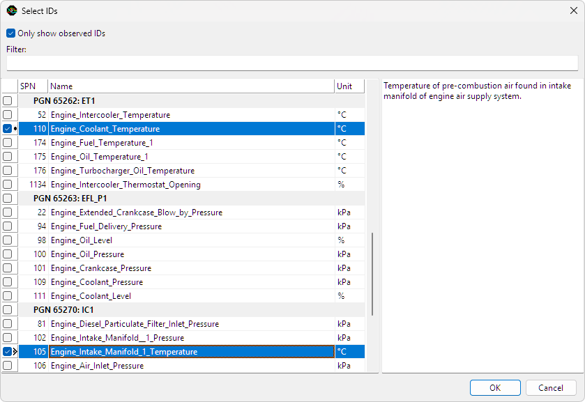
The dialog lists all J1939 standard Suspect Parameter Numbers (SPNs), ordered by Parameter Group Number (PGN). The text area at the right shows information about the highlighted PGN or SPN. When only show observed IDs is checked, the SPN list is reduced to only the ones contained in PGNs that were detected in the CAN input data.
To enable quick searching of parameters, further reducing the list is possible by using a filter string. Only PGNs and SPNs with a name satisfying the filter text are shown. By default, all filter keywords must be present in the name, but is also possible to exclude keywords by adding a minus symbol (-) in front of the keyword. The following filter for example will cause only PGNs and SPNs containing the word "temperature" but not "gas" to be listed:
temperature - gas
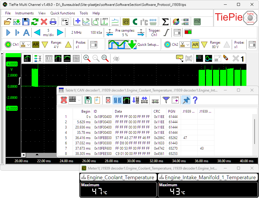
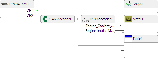
When all required IDs are selected, clicking the OK button will add an output for each selected ID. These outputs can be connected to meter sinks, table sinks, graphs and other I/Os for further processing.
Add output(s) from INI file
The J1939 standard leaves room for custom PGNs and SPNs. Manufacturers can use these to transfer information that is not covered in the J1939 standard. Custom outputs can be added to the J1939 decoder to extract this information, by loading SPN information from an INI file.
Each J1939 message contains an eight byte block of data, called a parameter group. This parameter group contains one or more suspect parameters. The INI file describes how they are encoded in the data and what their function, unit and valid ranges are. You can create an INI file section for each desired SPN as in the following example:
; Field extraction information for [PGN.SPN]:
[61444.190]
Name=Engine_Speed
Position=24
Size=16
Gain=0.125
Offset=0
Min=0
Max=8031.88
Unit=rpm
Explanation:
- [PGN.SPN] The section header contains the Parameter Group Number and the Suspect Parameter Number, separated by a dot.
- Name: name of the parameter. This will also be the name of the output of the J1939 decoder.
- Position: bit position at which this parameter starts, where the very first bit position is 0 (zero).
- Size: size in bits of this parameter.
- Gain: multiplication factor to determine the actual value from the binary data.
- Offset: offset value to be added after the gain operation to get the actual value.
- Min: minimum valid value (optional).
- Max: maximum valid value (optional).
- Unit: unit of the suspect parameter.
The example values result in a suspect parameter with PGN 61444 and SPN 190, called Engine_Speed, with a valid range of 0 to 8031.88 rpm and a resolution of 0.125 rpm.
Reset
The action Reset clears all data in the J1939 decoder I/O and removes all outputs.
Common properties and actions
Related information

Pulse decoder
The Pulse decoder I/O decodes the two signals from a quadrature encoder to a pulse count/position.
I2C decoder
The I2C decoder I/O decodes analog data on the SDA and SCL lines of an I2C bus to I2C data.
CAN decoder
The CAN decoder I/O decodes analog data to CAN data.
SPI decoder
The SPI decoder I/O decodes analog data on an SPI bus to SPI data.
LIN decoder
The LIN decoder I/O decodes analog data on a Local Interconnect Network bus to LIN message data.
SENT decoder
The SENT decoder I/O decodes analog signals on a SENT bus to SAE J2716 SENT messages.
FlexRay decoder
The FlexRay decoder I/O decodes analog data on a bus to FlexRay message data.
Base section to index
The Base section to index I/O "fills gaps" in data with the last known value.
Meter
The Meter sink performs various measurements on the source's data and displays the results in segment displays as well as gauge displays.