
The I2C decoder I/O decodes analog data on an I2C bus to I2C data. Just measure the Clock and Data lines of the I2C bus with a scope and connect the measuring channels to the I2C decoder I/O. The I2C decoder I/O has auto level detection and auto bus speed detection. The output of the I2C decoder I/O can be shown in a Table sink or passed on a to a Value extractor I/O.
The I2C decoder always needs two sources: the first connected source will be used as I2C SCL (clock) and the second connected source will be used as I2C SDA (data).
I2C communication uses 7 or 10 bit addresses, followed by a bit that indicates a read (1) or write (0) of that address. The I2C decoder displays the addresses in its output.
The following fields are extracted from the I2C communication and shown as a column in a table:
| Field name | Purpose | Default shown |
|---|---|---|
| Address (Dec) | The address in decimal notation | |
| Address (Hex) | The address in hexadecimal notation | |
| Address Ack | Indicating if the transmitted address was acknowledged | |
| R/W | Indicating if the data is read or written | |
| Data size | Indicating the size of the data | |
| Data (Hex) | The data in hexadecimal notation | |
| Data (Dec) | The data in decimal notation | |
| Data (ASCII) | The data in ASCII notation | |
| Data Ack | Indicating if the last data byte was acknowledged | |
| Flags | Indicating various different bus states |
To show or hide specific columns from the table, use the Select columns
( ) button
in the Table sink.
) button
in the Table sink.
Double clicking a row in the table will zoom the active graph in to the time frame corresponding to the table row.
The Value extractor I/O can be used to extract a specific value from the decoded data and present that in a graph, a meter or a table.
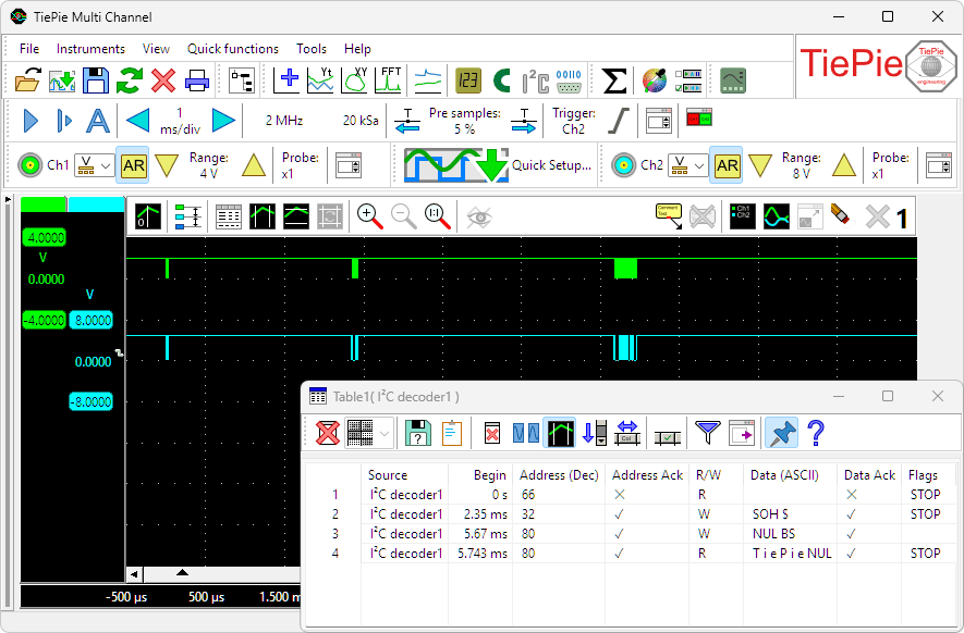
I2C decoder displaying multiple decoded read and write operations.
Properties and actions
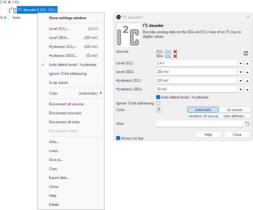
To control the behavior of the I2C decoder I/O, several properties and actions are available.
These can be accessed through a popup menu which is shown when the I/O is right clicked in the Object screen.
The properties can also be accessed through its settings window which is shown when the I/O is double clicked in the Object screen.
To open the Object screen, click the  Show object screen button.
By default, the settings window only shows the most used settings. When Advanced is ticked, the extended window with all settings is shown. See also the program settings.
Swap inputs
The I2C decoder always needs two sources: the first connected source will be used as I2C SCL and the second connected source will be used as I2C SDA. When the sources are connected the wrong way, the Swap inputs action will correct it.
Level (SCL) and Level (SDA)
In order to decode the analog signals into a digital signal, the I²C decoder I/O compares the analog input signals with mid levels: anything above that level is considered "high" and anything below that level is considered "low". The Level (..) properties set a mid level for the SCL and SDA signal individually.
Hysteresis (SCL) and Hysteresis (SDA)
To minimize the effect of noise on the signals when comparing the signals to the mid levels, a Hysteresis can be used around these levels. Anything above "level + hysteresis/2" is considered "high" and anything below "level - hysteresis/2" is considered "low". The Hysteresis (..) properties set the size of the hysteresis for the SCL and SDA signal individually.
Auto detect level and hysteresis
Enabling Auto detect level and hysteresis will let the software determine a suitable mid level and hysteresis, based on the measured signal. Each time new data is available, the suitable levels and hystereses will be determined again. In streaming mode, levels and hystereses are determined once based on the first chunk of data and remain at these values though out the whole measurement.
Auto detect level and hysteresis is default enabled.
Ignore 10 bit addressing
When I2C uses 10 bit addressing, the highest 5 bits in the address field contain 11110 as an indicator that 10 bit addressing is used. The next byte then also contains address information. When Ignore 10 bit addressing is enabled, this mechanism is ignored and the address byte is decoded as an 7 bit address and the next byte is treated as data byte.
Common properties and actions
Related information

Pulse decoder
The Pulse decoder I/O decodes the two signals from a quadrature encoder to a pulse count/position.
UART / Serial decoder
The UART / Serial decoder I/O decodes analog data on a UART, RS232, RS485, MIDI, DMX, LIN or other compatible serial bus to serial data.
CAN decoder
The CAN decoder I/O decodes analog data to CAN data.
J1939 decoder
The J1939 decoder I/O extracts SAE J1939 SPN values from CAN messages.
SPI decoder
The SPI decoder I/O decodes analog data on an SPI bus to SPI data.
LIN decoder
The LIN decoder I/O decodes analog data on a Local Interconnect Network bus to LIN message data.
SENT decoder
The SENT decoder I/O decodes analog signals on a SENT bus to SAE J2716 SENT messages.
DMX512 decoder
The DMX512 decoder I/O decodes analog signals on a DMX512 bus to DMX512 messages.
FlexRay decoder
The FlexRay decoder I/O decodes analog data on a bus to FlexRay message data.
Value extractor
The Value extractor I/O extracts a specific value from a decoded serial communication and makes it available for graphs, meters and tables.