Several different trigger settings are available which determine how the system will trigger on a signal. The trigger source setting of the instrument determines which trigger signals are used to trigger the instrument.
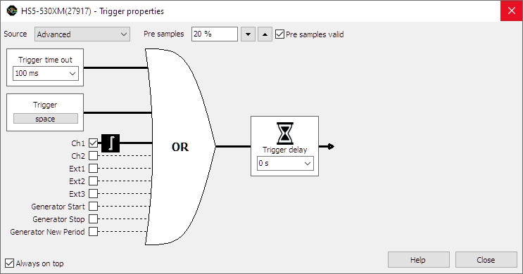
The trigger source can be set to a single channel or to any combination of channels or other trigger sources. The sources can be logically combined using an OR function. In the image below, the trigger source is set to Ch1 OR EXT1.
When no trigger source is selected, the trigger system is disabled and the instrument is free-running: it will start measuring the post samples directly.
Changing the trigger source
Changing the trigger source of an instrument in the Multi Channel oscilloscope software can be done in various different ways:
- Opening the Trigger properties dialog and selecting the required trigger source using the source selector. The option Advanced gives the possibility to set a combination of multiple trigger sources.
-
Clicking the trigger source label in the combined Time-out + Trigger source indicator
 on the instrument toolbar and selecting the required value from the popup menu.
-
Dragging the trigger symbol (

 , etc.)
from one axis to another axis in a graph.
, etc.)
from one axis to another axis in a graph.
- Right-clicking the instrument in the Object screen and selecting Trigger source and then the required value in the popup menu.
- Right-clicking the trigger symbol on an axis and selecting Move to and then the required value in the popup menu.
-
Using the Trigger source enable button
 on the channel toolbar for the required channel.
Trigger sources
Channel trigger
Channels can be used as trigger source. Channel triggers are configurable through Trigger type, Trigger level, Trigger hysteresis, Trigger condition and Trigger condition time properties.
Digital external
Besides the normal input channel triggers, most TiePie engineering instruments have an external trigger input, which can be used to connect a external digital trigger signal. Trigger level and hysteresis can not be set for this trigger input, but the edge (rising or falling) the system should react to can be set.
Generator-trigger
The WiFiScope WS5, Handyscope HS5 and Handyscope HS3 are equipped with an Arbitrary Waveform Generator. This generator has internal trigger signals that can be used as trigger source:
-
Generator Start
This signal is generated when continuous generation or burst generation is started, either by the Start button or by an external trigger signal. -
Generator New Period
This signal is generated when the whole buffer of the Arbitrary waveform generator has been processed and the Arbitrary waveform generator starts at the beginning of the buffer again. -
Generator Stop
This signal is generated when continuous generation of burst generation is stopped by the Stop button or burst generation is stopped because the required number of periods has been generated.