The Handyscope(s) opened by the Multi Channel oscilloscope software can be controlled in different ways. The most convenient way is to control the oscilloscopes and their channels by means of the toolbars, shown at the top of the main window.
Channels can also be controlled by means of popup menus and many settings are also accessible through hotkeys.
This page describes the channel toolbar. For configuring the oscilloscope, visit the page about the Oscilloscope toolbars.
Hardware instruments (Handyscopes) have settings that are divided into two groups: Oscilloscope settings, that affect all channels of the oscilloscope and Channel settings, which only influence a specific channel.
Using the channel toolbar
A channel toolbar is created for each oscilloscope channel. This convenient toolbar has large, clear, touchscreen friendly buttons for all channel settings, such as input range and coupling. It shows the current settings of the channel and allows to change all settings by clicking on the buttons.
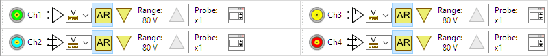
When a single instrument is detected and opened, with up to four input channels, all channel toolbars are shown together.
When a combined instrument is created and opened the channels of the combined instrument are grouped in a tab per sub instrument. This reduces the space occupied by the toolbars, leaving more space for the graph(s). it also simplifies adjusting a channel for a specific sub instrument in the combined instrument.
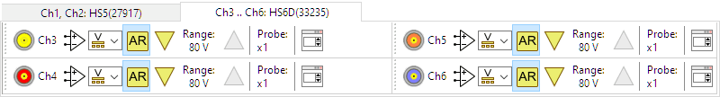
When an instrument with more than 4 channels is opened, the channel toolbars are arranged on tabs with each up to four channel toolbars.
The channel toolbar is fully configurable through the program settings. You can set the button size, add or remove buttons and change the order of the buttons.
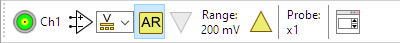
In the default setup, the channel toolbar contains the following items:
Channel settings dialog

Channel identification

SafeGround
The SafeGround button allows to select the state of the input channel:


For Handyscopes without SafeGround, the SafeGround button is not available.
Input coupling button

Auto ranging button

Increase/decrease input range
Two buttons are available to increase or decrease the input range:


The steps that are taken are the input ranges that are available in the input range menu of the oscilloscope channel.
These buttons are particularly useful on touchscreens.
Input range indicator

Probe

Additional buttons
Many more buttons and controls are available that can be placed on the channel toolbar. Refer to the settings for more info.
Input coupling AC and DC buttons
Two buttons are available to set the input coupling to a specific state:


Input range up/down

Input range selector

V/div input range indicator

Bandwidth limit

For Handyscopes without adjustable bandwidth limit, the bandwidth limit button is not available.
Channel invert

Increase/decrease trigger level
Two buttons are available to increase or decrease the trigger level for a channel:


The steps that are taken are 2.5%, where 100% equals the full range between +full scale and -full scale. 50% equals 0 V.
These buttons are particularly useful on touchscreens.
Increase/decrease trigger hysteresis
Two buttons are available to increase or decrease the trigger hysteresis for a channel:


The steps that are taken are 2.5%, where 100% equals the full range between +full scale and -full scale. One division equals 12.5%.
These buttons are particularly useful on touchscreens.
Trigger source on button

Create voltmeter button

Disconnect all sinks button

Real-time SureConnect connection test indicator
The image on this button reflects the current state of the real-time SureConnect connection test for a channel:


It requires real-time SureConnect connection test to be enabled.
For Handyscopes without SureConnect, the SureConnect connection test indicator is not available.