The channels of the oscilloscope(s) opened by the Multi Channel oscilloscope software can be controlled in different ways:
- by means of channel toolbars, located at the top of the window
-
through their settings window which is shown when
- the channel is double clicked in the Object screen
- the
 Settings window button on the channel toolbar is clicked
- by means of popup menus, opened by right clicking the channel in the Object screen or the channel indicator on the channel toolbars
Channels can also be controlled by means of channel toolbars, located at the top of the window. Many settings are also accessible through hotkeys.
Control instruments via a popup menu or settings window.
Channel settings and actions
An oscilloscope has one or more channels.
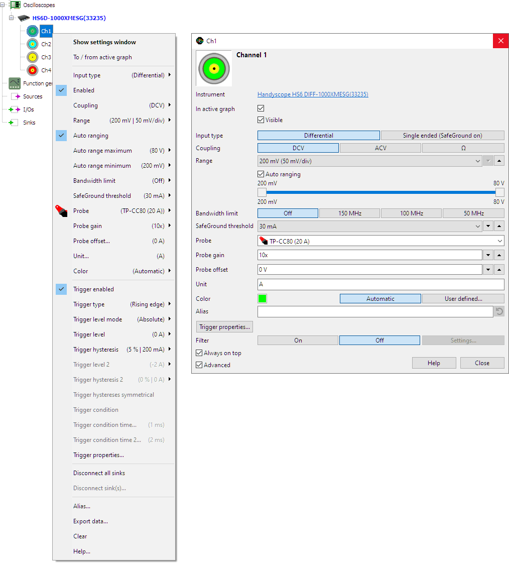
When a channel of an oscilloscope is right clicked, a popup menu is opened,
showing all settings and actions which are available for that channel.
Using the option Show settings window, a settings window is opened, which allows to changes all available settings.
The channel properties can also be accessed through its settings window which is shown when the channel is
double clicked or the
Settings window button on the channel toolbar is clicked.
When multiple channels are selected and then right-clicked, settings for all selected channels can be changed simultaneously via the popup menu to the same value. Actions will be performed on the selected channels.
Not all settings and actions are available for each Handyscope.
To/from active graph
Clicking this item will add the channel to the active graph. When the active graph already contains a line for this channel, it is removed from the graph.
The settings window uses 2 check boxes to control this:
- In active graph: this channel is present in the active graph or not
- Visible: this channel is visible in the active graph or not
When a channel is not present in the active graph, the Visible> check box is disabled.
Input type
When an instrument is equipped with the SafeGround option, the input type can be switched between Differential and Single-ended. When, in that case, the input is switched to single-ended, the SafeGround protection is enabled as well.
Enabled
This setting determines whether a channel is measuring or not. Enabling a channel allows to use that channel as a trigger source without displaying the channel in a graph. It can also affect the maximum sampling frequency of an oscilloscope. Enabling or disabling a channel does not add it to or remove it from a graph.
Coupling
This section of the channel popup menu has items to control the signal coupling of the channel. Hotkeys A and D can also be used to change the input coupling of a channel.
Range
To control the input range of the channel, items are available for each full scale input range setting. Hotkeys F5 and F6 can also be used to change the input range of a channel.
Auto ranging
To make the software select the most suitable input range, based on the input signal, use the Auto ranging setting. Hotkey R can also be used to change the auto range setting of a channel.
Auto range Maximum and Minimum
The auto ranging function can be limited to a certain range in which it is active. The settings Auto range maximum and Auto range minimum set the limits between which the function can operate.
In the settings window, the two settings are combined in a special dual slider, to set the limits.
The limits can be used when e.g. probing several points a circuit. Moving the probe from one point to another point will make the auto range function constantly switch to the most sensitive range, when the probe is temporarily not connected. Setting a lower limit close to the actual range will avoid that and make the scope respond faster when the probe is connected again.
Probe
Probes or current clamps connected to an input channel, usually require a compensation factor in the software, to let the input show the correct values. This can affect the probe gain and probe offset as well as the measurement unit.
The Probe setting allows to select which of the TiePie engineering probes or current clamps is connected to the input and in which setting it is set. The probe gain, probe offset and the measurement unit will then be set accordingly.
Probe gain
Probes connected to an input channel usually attenuate the input signal. Specialized probes or signal converters can also amplify the input signal. The probe gain setting allows to compensate the measured values for the gain applied by the probe or converter. The channel will then give the original signal values.
When e.g. a X10 attenuating oscilloscope probe is connected, the channel will measure a 10 times smaller value of the input signal. By setting the probe gain to 10, the measured values will be multiplied by 10 to compensate.
This item opens a sub menu where the probe gain of a channel can be selected from a number of predefined values and a User defined... setting.
Probe offset
Probes connected to an input channel usually attenuate the input signal. Specialized probes or signal converters can also add an offset to the input signal. The probe offset setting allows to compensate the measured values for the offset applied by the probe or converter. The channel will then give the original signal values.
Unit
This item sets the unit of the channel. The unit can be set to any (string) value. The unit will also be passed on to any connected I/O or Sink.
The default unit of a channel is V. When a different unit is selected, this unit will be "locked" and kept intact, even if a probe is selected that uses a different unit. To unlock a manually entered unit, clear the unit field. This will make the unit be taken from the channel default or the selected probe.
Color
For easy recognition, channels can have different colors. This selection opens a sub menu with two choices:
- Automatic - The color is selected from a group of channel colors which is set in the program settings
- User defined ... - A color picker is shown to select a color.
Trigger properties
The Trigger properties action opens the dedicated Trigger properties dialog, in which all trigger properties can be set.
Trigger enabled
This setting determines whether a channel is used as trigger source or not. When multiple channels are used as trigger source, they are OR'ed.
Trigger type
This item opens a sub menu which allows to set the trigger type of a channel.
Trigger level mode
Trigger level mode defines how the trigger level is set, either absolute or relative.
When the trigger level mode is set to Absolute, the trigger level is set as an absolute voltage, clipped by the full scale input range. When trigger level mode is set to absolute and auto ranging of the channel is enabled, the trigger level will remain at the same absolute voltage level when the input range changes. The input range will not auto range to a range that is smaller than the selected trigger level.
When the trigger level mode is set to Relative, the trigger level is set as percentage of the full scale input range:
- 100 % corresponds to positive full scale
- 50 % corresponds to 0 V
- 0 % corresponds to negative full scale
When the trigger level mode is set to Relative and auto ranging of the channel is enabled, the trigger level will remain at the same percentage when the input range changes, resulting in a different absolute voltage.
Trigger level
This item opens a sub menu which allows to set the trigger level of a channel. The trigger level is set as a percentage of the input range, where 100% corresponds with positive full scale and 0% with negative full scale. 50% corresponds to 0 V. Several default values are available in the menu, as well as a User defined... setting. Through this option, it is also possible to set the trigger level as a voltage value. Hotkeys F7 and F8 can also be used to change the trigger level of a channel.
Trigger hysteresis
This item opens a sub menu which allows to set the trigger hysteresis of a channel. The trigger hysteresis is set as a percentage of the input range, where 100% corresponds with the full input range from positive full scale to negative full scale. 12.5% corresponds to 1 division. Several default values are available in the menu, as well as a User defined... setting. Through this option, it is also possible to set the trigger level as a voltage value. Hotkeys [ and ] can also be used to change the trigger hysteresis of a channel.
Trigger level 2
Some trigger types use two trigger levels. This item controls the second trigger level, in the same way as the first trigger level.
Trigger hysteresis 2
Some trigger types use two trigger hystereses. This item controls the second trigger hysteresis, in the same way as the first trigger hysteresis.
Trigger condition
Some trigger types have an additional condition setting, which must be met to generate a trigger. This item opens a sub menu with the available trigger condition settings for the currently set trigger type.
Trigger condition time
A trigger condition can be time related. This item opens a sub menu where the trigger condition time can be selected from a number of predefined values and a User defined... setting.
Filter
To simplify filtering the measured signal of a channel, a Filter can be added behind the channel in the software, using the Filter setting.
Disconnect all sinks
This item immediately disconnects all I/Os, sinks and graph lines that are connected.
Disconnect sink(s)
This item shows a dialog with all connected I/Os, sinks and graph lines. A selection can be made of the sink(s) that need to be disconnected.
Alias
A channel can be given a descriptive name for easy recognition, e.g. "battery" when measuring a battery voltage. This is the alias of the channel. Select this item to set the alias of a channel. To clear the alias and restore the original name, enter an empty string.
Export data
With this item the measured data of a channel can be exported to a different file format, to use it in third party applications.
Clear
Use the Clear action to remove the measured data from a channel and fill it with 0 V.