A protocol analyzer is a measuring instrument that analyzes one or more signals that are used to communicate between electronic devices according a specific protocol. A protocol analyzer examines the signals and decodes the information that is transferred. De decoded information can be displayed in graphs, meter sinks and table sinks.
A protocol analyzer is a useful tool when developing a hardware and/or software implementation of a communication bus. It can also be used when debugging device or bus failures.
The Multi Channel oscilloscope software contains the following protocol analyzers:
 I2C
I2C UART / Serial
 CAN
CAN J1939
J1939 SPI
SPI LIN
LIN DMX512
 SENT
SENT FlexRay
I2C decoder
The I2C decoder in the Multi Channel oscilloscope software analyzes both I2C signals and displays the transferred messages. Besides I2C buses, it also supports related buses like SMBus, ACCESS.bus and TWI.
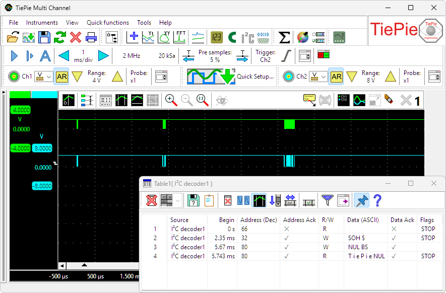
The I2C decoder uses the SDA and SCL signals from the I2C bus and translates these into a chronological list of all instructions including their data. The I2C decoder has the following features:
- 10 kbps, 100 kbps, 400 kbps, 1 Mbps and 3.4 Mbps support
- Missing ACK detection
- 7 and 10 bits addressing support
- Repeated start support
- Clock stretching support
UART / Serial decoder
The UART / Serial decoder in the Multi Channel oscilloscope software analyzes one or more serial signals and displays the transferred messages. It supports RS232 serial interfaces, as well as related interfaces like RS485, MIDI, DMX and other compatible buses.
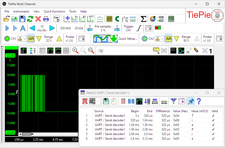
The UART / serial decoder can be used to simultaneously analyze and decode multiple communication signals. It features:
- Automatic baudrate detection and user defined baudrate setting
- Databits setting: 5, 6, 7, 8 or 9
- Parity setting: none, even, odd, mark or space
- Stopbits setting: 1, 1.5, 2, 2.5, 3, 3,4 or 4
CAN decoder
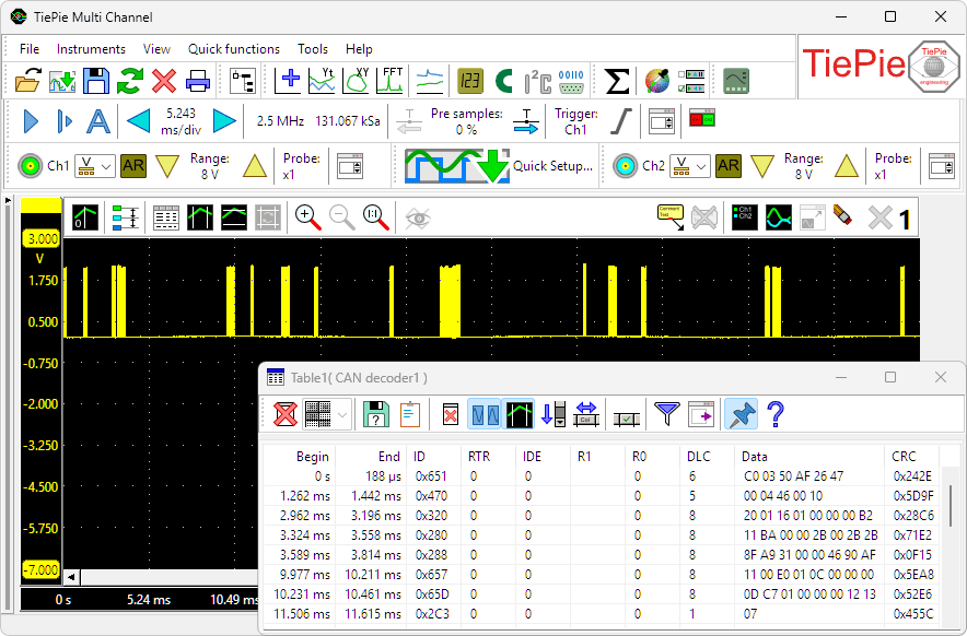
The CAN decoder in the Multi Channel oscilloscope software can be used to decode messages which are transmitted on a CAN bus. The source for the CAN decoder can either be the differential CAN signal or the CAN-high signal. All CAN bus bitrates are supported. Various fields from the CAN bus messages are decoded and can be displayed in a table as shown below.
J1939 decoder
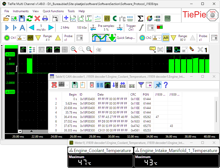
The J1939 decoder in the Multi Channel oscilloscope software extracts SAE J1939 SPN values from CAN messages. It has one input to receive CAN messages, from e.g. a CAN analyzer and can have multiple outputs. Each output contains the values of a single SPN (Suspect Parameter Number), selected from a database or loaded from a custom INI file. The data from these outputs can be used in graphs, meters, tables and by other I/Os.
SPI decoder
The SPI decoder in the Multi Channel oscilloscope software analyzes the Clock and Data signals on an SPI bus and displays the transferred messages.
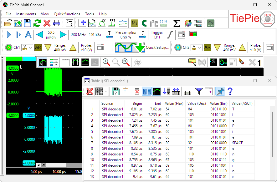
The SPI decoder has the following features:
-
Supports SPI modes
- 0 (Clock Polarity (CPOL) = 0, Clock Phase (CPHA) = 0)
- 1 (Clock Polarity (CPOL) = 0, Clock Phase (CPHA) = 1)
- 2 (Clock Polarity (CPOL) = 1, Clock Phase (CPHA) = 0)
- 3 (Clock Polarity (CPOL) = 1, Clock Phase (CPHA) = 1)
- Automatic bus speed detection
- Bit order setting: MSB first or LSB first
- Word size setting: 4, 8, 12, 16, 24, 32 bits or user defined
LIN decoder
The LIN decoder in the Multi Channel oscilloscope software decodes analog data on a Local Interconnect Network bus to LIN message data and displays the transferred messages.
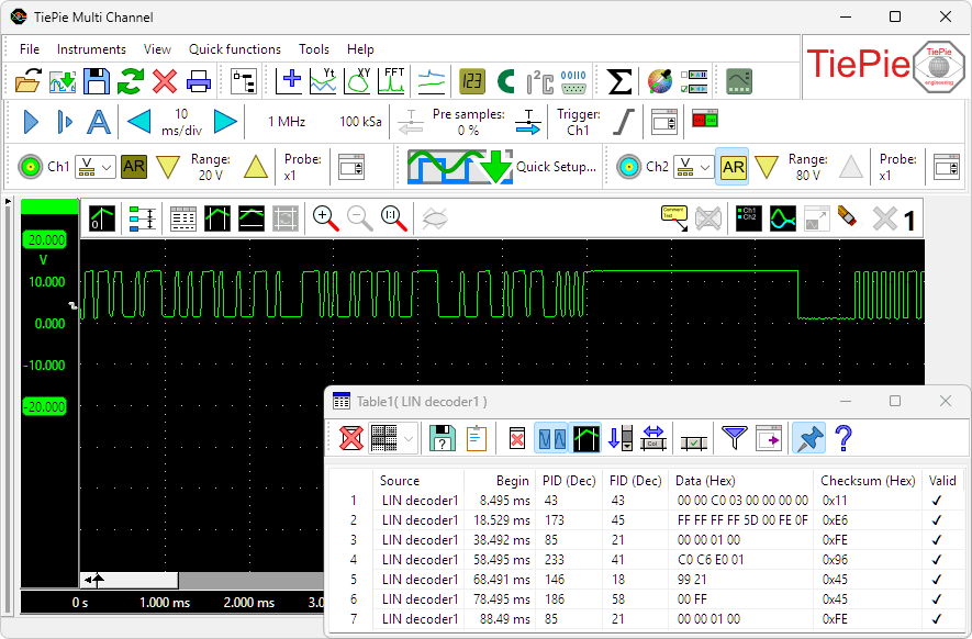
The LIN decoder has the following features:
- Automatic baudrate detection and user defined baudrate setting
- PID decoding
- FID decoding
- Checksum verification
- Parity verification
SENT decoder
The SENT decoder in the Multi Channel oscilloscope software decodes analog data on a SENT bus to SAE J2716 SENT message data and displays the transferred messages.
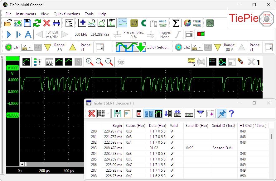
The SENT decoder has the following features:
- Automatic clock tick detection and user defined clock tick setting
- Automatic pause pulse detection and user defined pause pulse setting
- Data decoding
- Value decoding
- Checksum verification
DMX512 decoder
The DMX512 decoder in the Multi Channel oscilloscope software decodes analog data on a DMX512 bus to DMX512 message data and displays the transferred messages.
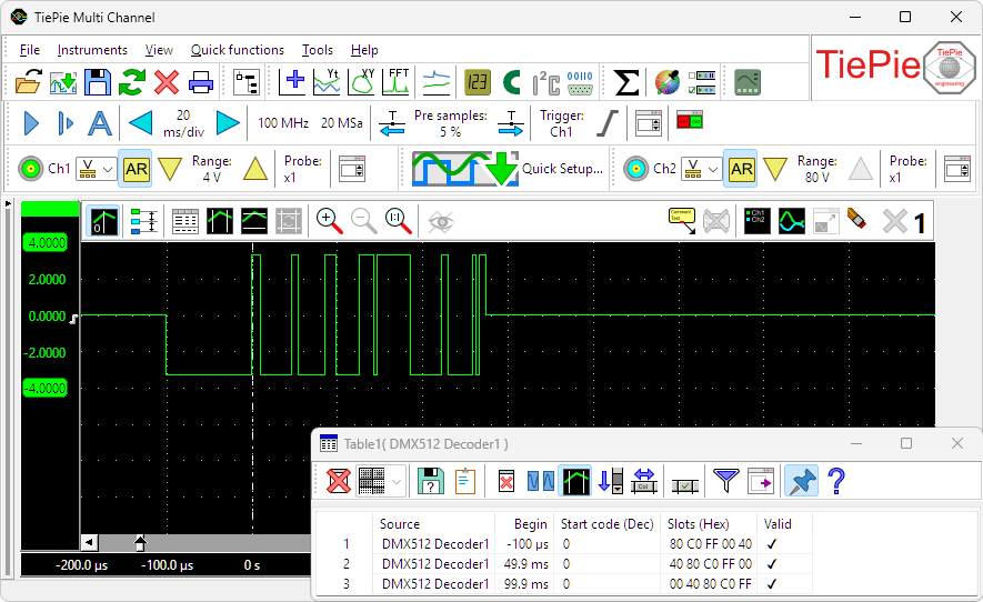
The DMX512 decoder has the following features:
- Automatic level and hysteresis settings
- Start code decoding
- Slots decoding
- Validity verification
FlexRay decoder
The FlexRay decoder decodes analog data on a bus to FlexRay message data and displays the transferred messages.
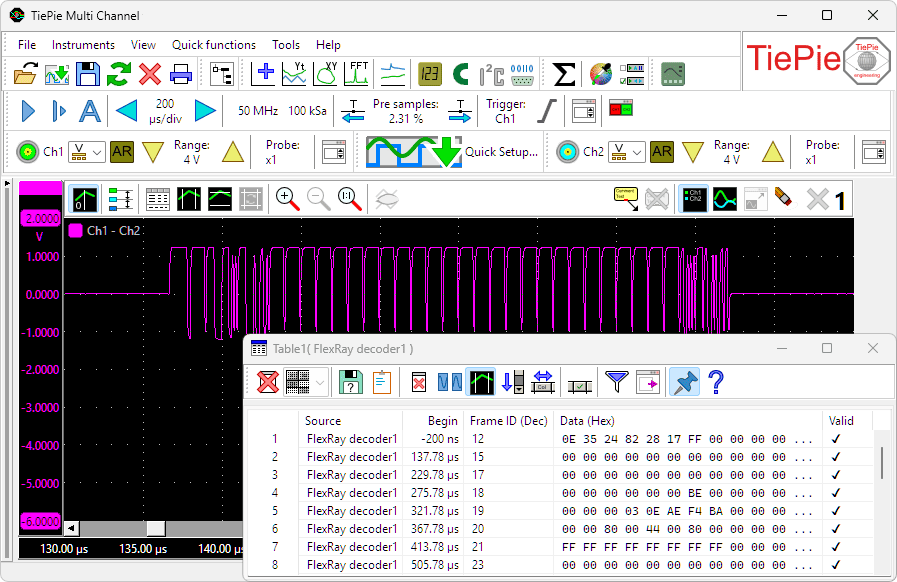
The FlexRay decoder has the following features:
- Automatic baud rate detection
- Supports channel A and channel B
- Automatic channel detection
- Validity verification
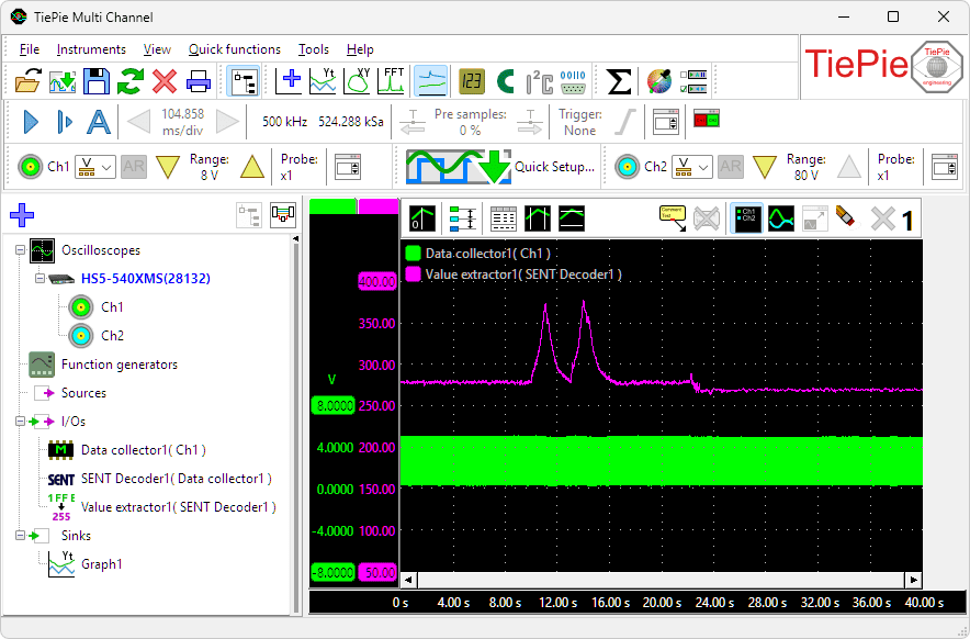
Value extractor

When a serial communication, like e.g. CAN, LIN or SENT is decoded, a stream of data is obtained. This data can be shown in a table, but it is much more useful if a specific value in that data stream can be isolated and monitored, either in a graph, in a meter or in a table. The Value Extractor I/O can be used to extract such values from the data stream and present them in a graph, meter and/or table sink.
The measurement below is performed in a car, on the SAE J2716 SENT bus, which connects sensors to the motor management system. In this measurement the communication from a pressure sensor is monitored and decoded by a SENT decoder I/O. The engine is running and the throttle pedal is pressed twice. Placing the extracted data in a table would generate a lot of numbers, making it difficult to see what actually happens. By using a Value extractor I/O and selecting the proper value from the data stream and showing its values in a graph makes perfectly visible what the pressure does when the throttle pedal is pressed.
The Value extractor has the following features:
- Filter specific messages from the stream, based on read or write, address, ID, etc.
- Extract protocol specific values or generic values
- Convert extracted values to show them in a specific unit
The Value extractor I/O can be used with all protocol decoders. When connected to a CAN decoder, it can extract plain CAN values, but also J1939 values and CANopen values.