
The SAE J2716 SENT (Single Edge Nibble Transmission) protocol is a point-to-point system for transmitting sensor values to a controller in a vehicle. The SENT decoder I/O decodes analog signals to SENT messages. The SENT decoder has auto level detection and auto clock tick detection. The output of the SENT decoder I/O can be shown in a Table sink or passed on a to a Value extractor I/O.
The following fields are extracted from the SENT communication and shown as a column in the table:
| Field name | Purpose | Default shown |
|---|---|---|
| Status (Hex) | Status of the message, in hexadecimal | |
| Status (Bin) | Status of the message, in binary | |
| Data (Hex) | Transmitted data, in hexadecimal | |
| Data (Dec) | Transmitted data, in decimal | |
| Checksum (Hex) | Checksum, in hexadecimal | |
| Checksum (Dec) | Checksum, in decimal | |
| Checksum valid | Flag to indicate if checksum is valid | |
| Valid | Validity of the message | |
| Flags | ||
| Serial ID (Hex) | ||
| Serial ID (Dec) | ||
| Serial ID (ASCII) | ||
| Serial value (Hex) | ||
| Serial value (Dec) | ||
| Serial value (ASCII) |
Additionally, many other fields can be extracted from the SENT communication. These are specific fields, which can be used with certain sensors. Refer to the documentation of the sensor to find out which fields are useful to place in the table.
To show or hide specific columns from the table, use the Select columns
( ) button
in the Table sink.
) button
in the Table sink.
Double clicking a row in the table will zoom the active graph in to the time frame corresponding to the table row.
The Value extractor I/O can be used to extract a specific value from the decoded data and present that in a graph, a meter or a table.
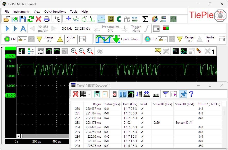
Measurement on a SENT bus, with data decoded by a SENT decoder.
SENT decoder properties
To control the behavior of the SENT decoder I/O, several properties and actions are available.
These can be accessed through a popup menu which is shown when the I/O is right clicked in the Object screen.
The properties can also be accessed through its settings window which is shown when the I/O is double clicked in the Object screen.
To open the Object screen, click the  Show object screen button.
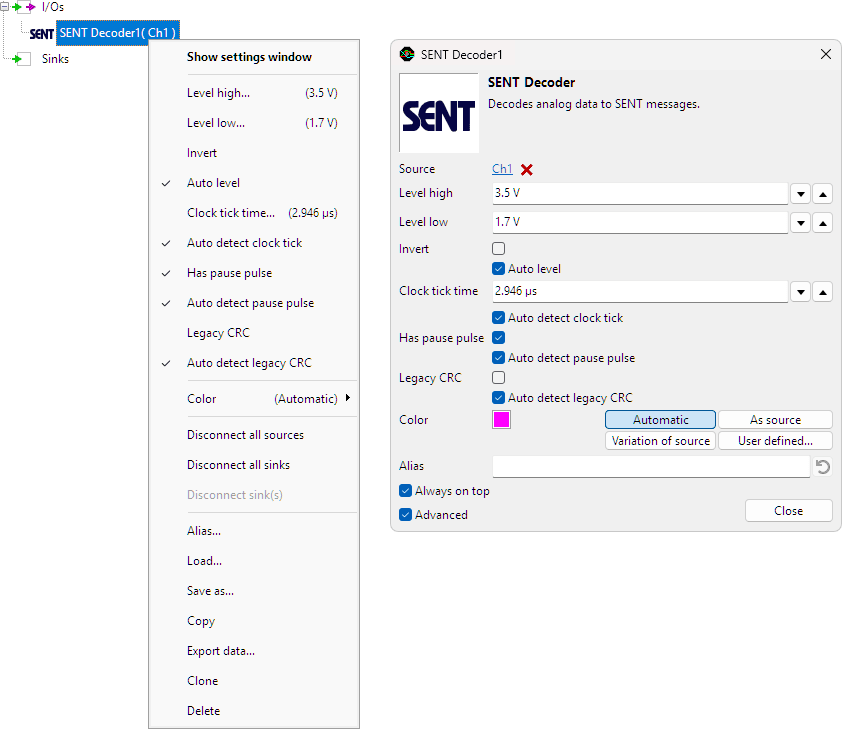
By default, the settings window only shows the most used settings. When Advanced is ticked, the extended window with all settings is shown. See also the program settings.
Level high and Level low
In order to decode the analog signal into a digital signal, the SENT decoder I/O compares the analog input signal with two levels, High and Low level: anything above the High level is considered "high" and anything below the Low level is considered "low".
Auto level
Enabling Auto level will let the software determine a suitable High level Low level, based on the measured signal. Each time new data is available, the suitable levels will be determined again. In streaming mode, the levels are determined once based on the first chunk of data and remain at these values though out the whole measurement.
Auto level is default enabled.
Invert
For correct detection, the Invert property must be set to the correct value, corresponding to the bus that is under measurement.
- When Invert is disabled levels above high level are logic 1, levels below low level are logic 0
- When Invert is enabled levels above high level are logic 0, levels below low level are logic 1
Invert is default off.
Clock tick time
In the SENT protocol, data is sent as a series of pulses, where the time between the falling edges of pulses determines the value of a nibble (4 bits). The time between the falling edges of pulses is measured in "ticks". A tick is the basic unit of time in SENT.
In order to decode the data, the SENT decoder needs to know the tick length or tick time.
Auto detect clock tick
Enabling Auto detect clock tick will let the software determine a Clock tick time, based on the measured signal. Each time new data is available, the Clock tick time will be determined again. In streaming mode, the Clock tick time is determined once based on the first chunk of data and remains at this values though out the whole measurement.
Has pause pulse
SENT messages are usually 32 bits long (8 nibbles) and consist of 6 nibbles of data, a nibble for CRC error detection and a nibble for status information. Optionally, SENT messages can be 5 nibbles long: 3 nibbles for data, one nibble for CRC error checksum and one nibble for status information. Optionally, a pause puls can be added to compensate for the varying length of the messages.
By enabling the option Has pause pulse, the decoder is told that the measured SENT signals contain pause pulses. If the decoded messages contain many invalid messages, it can be useful to change this setting, in order to get better decoding.
Auto detect pause pulse
Enabling Auto detect pause pulse will let the software determine the presence of a pause pulse, based on the measured signal. Each time new data is available, the presence of a pause pulse will be determined again. In streaming mode, the presence of a pause pulse is determined once based on the first chunk of data and remains at this values though out the whole measurement.
Legacy CRC
Each SENT message is transmitted with a CRC checksum, to verify that all data is received correctly. Originally, a certain algorithm was used to determine the CRC checksum. Later, a new algorithm was implemented.
Enabling Legacy CRC forces the SENT decoder to use the old CRC calculation algorithm. If the decoded messages contain many invalid messages, it can be useful to change this setting, in order to get better decoding.
Auto detect legacy CRC
Enabling Auto detect legacy CRC will let the software determine whether legacy CRC is used, based on the measured signal. Each time new data is available whether legacy CRC is used will be determined again. In streaming mode, the whether legacy CRC is used is determined once based on the first chunk of data and remains at this values though out the whole measurement.
Common properties and actions
Related information

I2C decoder
The I2C decoder I/O decodes analog data on the SDA and SCL lines of an I2C bus to I2C data.
UART / Serial decoder
The UART / Serial decoder I/O decodes analog data on a UART, RS232, RS485, MIDI, DMX, LIN or other compatible serial bus to serial data.
CAN decoder
The CAN decoder I/O decodes analog data to CAN data.
J1939 decoder
The J1939 decoder I/O extracts SAE J1939 SPN values from CAN messages.
SPI decoder
The SPI decoder I/O decodes analog data on an SPI bus to SPI data.
LIN decoder
The LIN decoder I/O decodes analog data on a Local Interconnect Network bus to LIN message data.
DMX512 decoder
The DMX512 decoder I/O decodes analog signals on a DMX512 bus to DMX512 messages.
FlexRay decoder
The FlexRay decoder I/O decodes analog data on a bus to FlexRay message data.
Value extractor
The Value extractor I/O extracts a specific value from a decoded serial communication and makes it available for graphs, meters and tables.