Contents
Introduction
Most oscilloscopes are equipped with a trigger circuit to start measuring when a certain condition occurs in the input signal. Triggering is used both for capturing unique signal events and to stabilize the display of repetitive signals. Without triggering, signals are measured and displayed at random times. The trigger circuit has several settings which are divided into instrument trigger settings and channel trigger settings.
Trigger properties dialog
Most trigger settings are combined in the Trigger properties dialog.
To open the trigger properties dialog, click the
 Trigger properties button on the instrument toolbar.
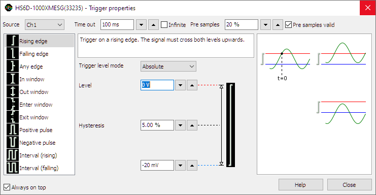
The trigger properties dialog allows to view and control instrument and channel trigger settings.
Additionally, it gives an explanation on the selected trigger type and examples that do cause a trigger (left column)
and do not cause a trigger (right column).
There is a dialog available for each opened instrument.
Trigger properties button on the instrument toolbar.
The trigger properties dialog allows to view and control instrument and channel trigger settings.
Additionally, it gives an explanation on the selected trigger type and examples that do cause a trigger (left column)
and do not cause a trigger (right column).
There is a dialog available for each opened instrument.
Instrument trigger settings
This section treats the instrument trigger settings. These settings affect the whole instrument, as opposed to the channel trigger settings, which affect only one channel of the instrument.
Trigger source
Several different trigger settings are available which determine how the system will trigger on a signal. The trigger source setting of the instrument determines which trigger signals are used to trigger the instrument.
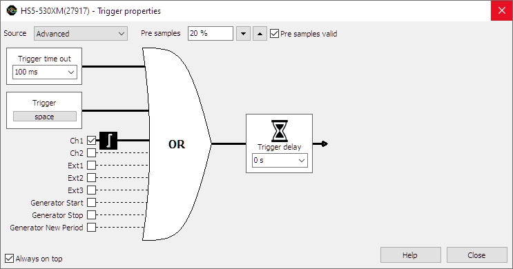
The trigger source can be set to a single channel or to any combination of channels or other trigger sources. The sources can be logically combined using an OR function. In the image below, the trigger source is set to Ch1 OR EXT1.
When no trigger source is selected, the trigger system is disabled and the instrument is free-running: it will start measuring the post samples directly.
Changing the trigger source
Changing the trigger source of an instrument in the Multi Channel oscilloscope software can be done in various different ways:
- Opening the Trigger properties dialog and selecting the required trigger source using the source selector. The option Advanced gives the possibility to set a combination of multiple trigger sources.
-
Clicking the trigger source label in the combined Time-out + Trigger source indicator
 on the instrument toolbar and selecting the required value from the popup menu.
-
Dragging the trigger symbol (

 , etc.)
from one axis to another axis in a graph.
, etc.)
from one axis to another axis in a graph.
- Right-clicking the instrument in the Object screen and selecting Trigger source and then the required value in the popup menu.
- Right-clicking the trigger symbol on an axis and selecting Move to and then the required value in the popup menu.
-
Using the Trigger source enable button
 on the channel toolbar for the required channel.
Trigger sources
Channel trigger
Channels can be used as trigger source. Channel triggers are configurable through Trigger type, Trigger level, Trigger hysteresis, Trigger condition and Trigger condition time properties.
Digital external
Besides the normal input channel triggers, most TiePie engineering instruments have an external trigger input, which can be used to connect a external digital trigger signal. Trigger level and hysteresis can not be set for this trigger input, but the edge (rising or falling) the system should react to can be set.
Generator-trigger
The WiFiScope WS5, Handyscope HS5 and Handyscope HS3 are equipped with an Arbitrary Waveform Generator. This generator has internal trigger signals that can be used as trigger source:
-
Generator Start
This signal is generated when continuous generation or burst generation is started, either by the Start button or by an external trigger signal. -
Generator New Period
This signal is generated when the whole buffer of the Arbitrary waveform generator has been processed and the Arbitrary waveform generator starts at the beginning of the buffer again. -
Generator Stop
This signal is generated when continuous generation of burst generation is stopped by the Stop button or burst generation is stopped because the required number of periods has been generated.
Pre trigger / Pre samples
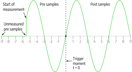
With digital storage oscilloscopes, the record length determines the number of samples that are measured. All these samples can be measured after the trigger has occurred. It is however possible to measure (a part of) the record before the trigger occurs, by selecting pre samples.
The total record will then be divided in a pre trigger part and a post trigger part, respectively containing pre samples and post samples. This way it is possible to "look back in time" since the pre samples were captured before the trigger moment.
With the TiePie engineering instruments it's possible to define the trigger moment at any position in the record.
Changing the trigger moment in the Multi Channel oscilloscope software can be done in various different ways:
-
By clicking the increase/decrease pre trigger percentage buttons
 and
and
 on the instrument toolbar.
-
Opening the instrument settings dialog using the
 Instrument settings dialog button and selecting the required pre trigger setting in the dialog.
- By using hotkeys Shift + ← and Shift + →.
- By dragging the small triangle on the slider in the horizontal scrollbar under the graph displaying signals from the instrument left or right. The position of the triangle in the scrollbar represents the trigger moment in the measured record.
-
By using the pre samples turning knob
 on the instrument toolbar.
- By right-clicking the horizontal scrollbar under the graph displaying signals from the instrument and selecting Pre trigger and then the appropriate pre trigger percentage in the popup menu.
- By right-clicking the instrument in the Object screen, selecting Pre trigger and then the appropriate pre trigger percentage in the popup menu.
Pre samples valid
When measuring pre samples, there are two possible moments to enable the trigger system:
- Pre samples valid enabled: when number of pre samples are measured after starting the measurement.
- Pre samples valid disabled: immediately when starting the measurement
Pre samples valid enabled
When the trigger system is enabled after measuring number of pre samples after starting the measurement, and a trigger occurs, all pre samples will be measured and will show the actual signal.
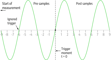
The advantage of enabling the trigger system after number of pre samples is that all pre samples are valid and no confusion may rise. A disadvantage of enabling the trigger system number of pre samples is that during measuring the pre samples, the trigger system is not active yet. If a trigger occurs while still measuring the pre samples, this trigger is ignored and the measurement not captured. When measuring a periodical signal this may not be a problem, but when trying to capture an intermittent phenomenon this may be a big problem.
Pre samples valid disabled
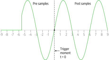
When the trigger system is enabled immediately after starting the measurement, and the first trigger occurs before number of pre samples are measured, a part of the pre samples remains unmeasured. These samples are drawn in the graph as 0 V, at the left hand side of the graph. At the moment the measurement was started, the signal "jumps" to the actual signal value.
The advantage of enabling the trigger system immediately after starting the measurement is that a trigger is never missed. A disadvantage of enabling the trigger system immediately after starting the measurement is that a part of the signal is drawn at 0 V, which may be confusing.
Not all TiePie engineering instruments support the setting Pre samples valid. When it is not supported, the trigger system is enabled immediately after starting the measurement.
Trigger delay
Trigger delay allows to start measuring a specified time after the trigger occurred. This allows to capture events that are more than one full record length past the trigger moment. Changing the trigger delay in the Multi Channel oscilloscope software can be done in several ways:
- Opening the trigger properties dialog, selecting trigger source "Advanced" and adjusting the trigger delay.
- Right-clicking the instrument in the Object screen and selecting Trigger delay in the popup menu. The delay can then be set by entering the required value in seconds.
Trigger time-out
Once the trigger conditions are set and the measurement is started, the instrument will wait until the trigger conditions are met before the post samples are measured and the measurement is finalized.
If the trigger conditions are set in such a way that the input signal(s) will never meet the trigger settings, the instrument will wait forever. When no measurement is performed, no signals will be displayed.
To avoid that the system will wait infinitely, a trigger time-out is added to the trigger system. When after a user defined amount of time after starting the measurement still no trigger has occurred, the trigger time-out will force a trigger. This will ensure a minimum number of measurements per second. On conventional desktop oscilloscopes, this is called Trigger mode AUTO and the used value is approximately 20 ms.
The trigger time-out is entered as a number, representing the delay in seconds. There are two special values for the trigger time-out setting:
-
trigger time-out = 0
Immediately after starting a measurement a trigger is forced. Basically this bypasses the trigger system and the instrument always measures immediately. No pre samples are recorded. The instruments is free-running, just like when no trigger source is selected. -
trigger-time-out = infinite
The system will wait infinitely for a trigger. The software will never force a trigger, only when the trigger conditions are met, a trigger will occur and a measurement will take place. This setting is particularly useful for one shot / single shot measurements. On conventional desktop oscilloscopes, this is called Trigger mode NORM.
Changing the trigger time-out of a channel in the Multi Channel oscilloscope software can be done in various different ways:
- Opening the trigger properties dialog and adjusting the trigger time-out.
-
Clicking the
 button on the instrument toolbar or
pressing hotkey W will toggle the trigger time-out between the set value and infinite.
button on the instrument toolbar or
pressing hotkey W will toggle the trigger time-out between the set value and infinite.
-
Clicking the
 button on the instrument toolbar or
pressing hotkey 1 will toggle the trigger time-out between the set value and 1 second.
button on the instrument toolbar or
pressing hotkey 1 will toggle the trigger time-out between the set value and 1 second.
-
Clicking the
 button on the instrument toolbar or
pressing hotkey 0 will toggle the trigger time-out between the set value and zero.
button on the instrument toolbar or
pressing hotkey 0 will toggle the trigger time-out between the set value and zero.
Force a trigger
Besides using the available trigger sources and the trigger time-out to start a measurement, it is also possible to stop waiting for the trigger time out and to start measuring the post samples right away by forcing the trigger of the instrument.
Forcing a trigger of an instrument in the Multi Channel oscilloscope software can be done in different ways:
- Using hotkey space bar.
-
Using the Trigger now! button
 on the instrument toolbar.
Channel trigger settings
Channel trigger circuits monitor the channels continuously and generate a trigger signal when the input signals meet some predefined trigger condition. To change this condition, several channel trigger settings are available which can be adjusted for all channels individually.
Trigger type
There are several different trigger types:
| Trigger type | Description |
|---|---|
| edge trigger | trigger on an rising, falling or any edge in the signal |
| window trigger | trigger when the signal enters or leaves a certain window or range, optionally shorter/longer than a specified time |
| pulse width trigger | trigger on a positive or negative pulse in the signal wider/narrower than a specified width, or inside/outside a specified time frame |
| interval trigger | trigger on a periodical signal with a period time shorter/longer than a specified length, or inside/outside a specified time frame |
Changing the trigger type of a channel in the Multi Channel oscilloscope software can be done in various different ways:
- Opening the trigger properties dialog and selecting the required trigger type from the list of available trigger types.
- Right-clicking the trigger symbol on an axis and selecting Trigger type and then the required value in the popup menu.
-
Double-clicking the trigger symbol to toggle between:
Without Ctrl With Ctrl 


- Right-clicking the channel in the Object screen and selecting Trigger type and then the required value in the popup menu.
Trigger level mode
The Trigger level mode defines how the trigger level is set. Trigger level mode can be set to one of two values:
- Relative: the trigger level is set as a percentage of the full scale input range
- Absolute: the trigger level is set as an absolute voltage value, independent of the input range.
Trigger level mode is a channel setting, it can be set for each channel individually. Trigger level mode is set to Absolute by default.
Absolute trigger level
When Trigger level mode is set to Absolute, the trigger level is set as an absolute voltage value, independent of the input range. When the input range changes, either by setting it to a different range, or by auto ranging because the input signal changes, the trigger level will remain at the same absolute voltage level. When the trigger level is set to a value outside the current input range, the input range will be increased to make the trigger level fit. The input range cannot be set to a lower value than the currently set trigger level.
Relative trigger level
When Trigger level mode is set to Relative, the trigger level is set as a percentage of the full scale input range:
- 100 % corresponds to a trigger level at positive full scale of the input range,
- 50 % corresponds to a trigger level at 0 V,
- 0 % corresponds to a trigger level at negative full scale of the input range.
When the input range changes, either by setting it to a different range, or by auto ranging because the input signal changes, the trigger level will remain at the same percentage of the full scale input range. This means that the voltage at which the trigger level is set will change.
Setting the trigger level mode
Setting the trigger level mode can be done by right-clicking the channel in the Object screen and then selecting Trigger level mode and the required value from the popup menu.
Trigger level
All oscilloscope channel trigger types use one or two trigger levels. Trigger levels can be set for each channel individually. The trigger level is set either in absolute values or in relative values, depending on the selected Trigger level mode. Changing a trigger level of a channel in the Multi Channel oscilloscope software can be done in several ways:
-
Dragging/moving the trigger symbol
(,
, etc.) on an
axis of an oscilloscope channel that is used as trigger source.
The trigger level can be changed by moving the edge of the symbol associated with the level,
or by moving the whole symbol.
- Opening the trigger properties dialog and adjusting the required trigger level(s).
- Right-clicking the trigger symbol on an axis or the associated channel in the Object screen and selecting Trigger level or Trigger level 2 in the popup menu. The level can then be set by selecting one of the pre defined values. A User defined... setting is available that also allows to an arbitrary value.
- Using hotkeys F7 and F8 in combination with the appropriate channel selection hotkey(s) (only trigger level 1).
-
Clicking the increase/decrease trigger level buttons
 and
and
 on the channel toolbar (only trigger level 1).
Trigger hysteresis
All oscilloscope channel trigger types use one or two trigger hystereses. The hysteresis defines the distance between the firing level and the arming level and determines the sensitivity of the trigger system. A small hysteresis means that the arming and firing level are close to each other and a small signal change will be enough to cause a trigger. A large hysteresis means that the signal change must be large before a trigger is generated. This makes the trigger system less sensitive to noise.
Trigger hysteresis can be set for each channel individually. Changing the trigger hysteresis of a channel in the Multi Channel oscilloscope software can be done in various different ways:
-
Dragging/moving an edge of the trigger symbol
(,
, etc.)
on an axis of an oscilloscope channel that is used as
trigger source.
- Opening the trigger properties dialog and adjusting the required trigger hysteresis.
- Right-clicking the trigger symbol on an axis or the associated channel in the Object screen and selecting Trigger hysteresis or Trigger hysteresis 2 in the popup menu. The hysteresis can then be set as a percentage of the full scale input range of the channel by selecting one of the pre defined percentage values. The corresponding voltage is also displayed. A User defined... setting is available that also allows to set the trigger hysteresis as a voltage.
- Using hotkeys [ and ] in combination with the appropriate channel selection hotkey(s) (only trigger hysteresis 1).
-
Clicking the increase/decrease trigger hysteresis buttons
 and
and
 on the channel toolbar (only trigger hysteresis 1).
Trigger condition
Several oscilloscope channel trigger types can have an additional trigger condition and corresponding trigger condition time. Some trigger conditions have two trigger times, defining a trigger condition time frame. The following trigger conditions are available:
| Trigger condition | Description |
|---|---|
| None | there is no additional trigger condition. |
| Shorter than | the signal requirements defined by the trigger type must last shorter than the specified trigger condition time to cause a trigger. |
| Longer than | the signal requirements defined by the trigger type must last longer than the specified trigger condition time to cause a trigger. |
| Inside | the length that the signal requirements defined by the trigger type last, must be inside the trigger condition time frame to cause a trigger. |
| Outside | the length that the signal requirements defined by the trigger type last, must be shorter than or longer than the trigger condition time frame, in other words outside the trigger condition time frame to cause a trigger. |
Setting the trigger condition in the Multi Channel oscilloscope software can be done in several ways:
- Using the Condition selector in the trigger properties dialog.
- Right-clicking the trigger symbol on an axis or the associated channel in the Object screen and selecting Trigger condition and then the required value in the popup menu.
Trigger condition time(s)
The trigger condition time specifies the duration of a specific signal condition, in seconds. When two trigger condition times are available, the two times define a trigger condition time frame, in seconds.
Setting the trigger condition time(s) in the Multi Channel oscilloscope software can be done in several ways:
- Entering the required value in the Condition time or Condition time 2 box in the trigger properties dialog.
- Right-clicking the trigger symbol on an axis or the associated channel in the Object screen and selecting Trigger condition time or Trigger condition time 2 in the popup menu. The time is entered in seconds.