December 2, 2020
Version 1.43 of the Multi Channel oscilloscope software is now available for download.
Various changes have been made to add new functionality and to improve basic operations in the software. This is a categorized overview of some of the changes.
Contents
Settings windows for instruments, channels and I/Os
All instruments and channels now can also be controlled using dedicated instrument settings
windows and channel settings windows.
These windows are opened by clicking the
 Settings window button on the instrument or channel toolbar.
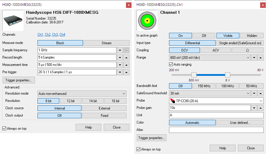
The Auto ranging function of the channels now also have a lower and upper limit between which the auto ranging function can operate. The limits can be used when e.g. probing several points a circuit. Moving the probe from one point to another point will make the auto range function constantly switch to the most sensitive range, when the probe is temporarily not connected. Setting a lower limit close to the actual range will avoid that and make the scope respond faster when the probe is connected again.
Sources and I/Os now also have dedicated settings windows for easy control of the objects. Their settings windows are opened by double clicking the source or I/O in the object screen, or by right-clicking the source or I/O and selecting Show settings window from the popup menu.

The settings windows show all relevant settings of the instrument, channel or I/O it belongs to. Changes made in the settings window are executed immediately on the corresponding object. The settings windows can be left open while measuring to keep easy access to all settings of the objects.
New signal processing I/Os added
A number of new I/Os have been added to the software, to help process your signal and get the most information from it.
Filter I/O
A new Filter I/O is added to the software, replacing the existing Low Pass filter I/O. A typical application of the Filter I/O is to remove unwanted frequencies from a measurement, which may negatively affect further operations on the measured signal.
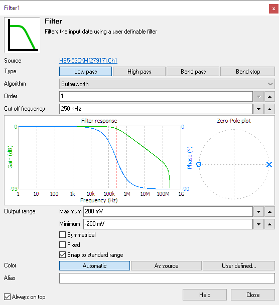
The fully configurable Filter I/O can be set to one of the following types:
- Low pass filter
- High pass filter
- Band pass filter
- Band stop filter
Depending on the selected filter type, one out of three or four filter algorithms can be selected. Available filter algorithms are:
- Butterworth
- Chebyshev type I
- Chebyshev type II
- Peak (band pass only)
- Notch (band stop only)
The Filter I/O settings window also shows a graphical representation of the filter characteristics. A graph with gain and phase is shown as well as a Zero-Pole plot. The Phase graph can be switched between degrees and radians by clicking the axis legend. The frequency axis be switched between linear and logarithmic by clicking the axis legend.
Signal cleaner I/O
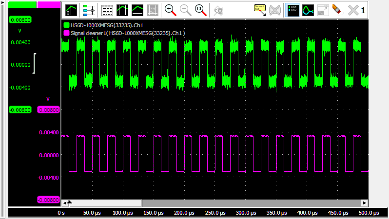
A Signal cleaner I/O is added to the software, to clean up periodical signals by removing noise and other distortions from the measured signals. The cleaning strength is adjustable.
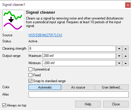
Below an example of a 3 mV square wave with significant noise, cleaned up using the Signal cleaner I/O.
Deskew I/O
A Deskew I/O is added to the software, to be able to shift a signal horizontally, in time.
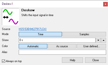
The Deskew I/O is used to place two signals with a phase shift on top of each other in the scope screen. The Deskew I/O can also be used to remove a phase shift from a current signal, caused by a current probe, in order to perform correct power calculations.
The Deskew I/O can be used to shift signals from channels but also from other sources like I/Os. The skew can be set in time or in a number of samples, both in positive and negative direction.
Ideal filter
Another filtering I/O has been added to the software, the Ideal filter I/O. The Ideal filter I/O filters the source's data using an ideal user definable software filter. It fully passes all wanted frequencies in the frequency spectrum and fully blocks all unwanted frequencies in the frequency spectrum. The edges of the filter are infinitely steep.
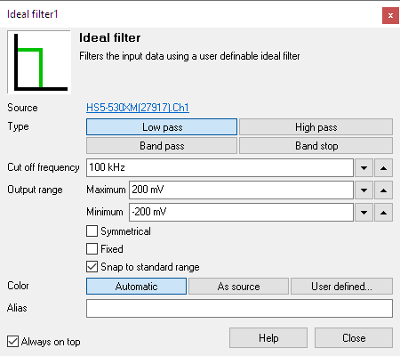
The fully configurable Ideal Filter I/O can be set to one of the following types:
- Low pass filter
- High pass filter
- Band pass filter
- Band stop filter
Window I/O
A Window I/O is added to the software. The Window I/O applies a window function to its input signal. The window function changes the magnitude of the samples of in input signal, such that the ends smoothly taper to zero. A typical application of the Window I/O is to remove spectral leakage in a frequency spectrum using a Fourier Transform. A second application is to shape signal bursts, e.g. to use in the Arbitrary Waveform Generator.
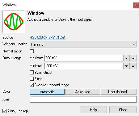
Settings are available to select the used window function and whether the output should be normalized.
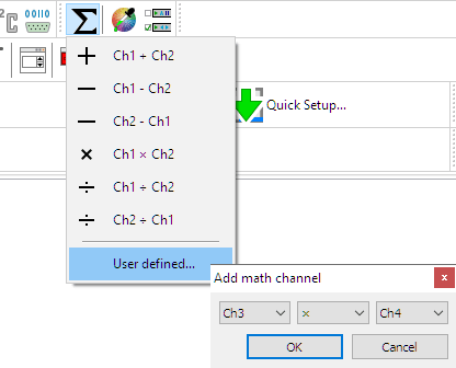
New option in the Math menu
The Math menu in the software has been expanded with a User defined... setting that opens a wizard to do a calculation on two arbitrary channels.
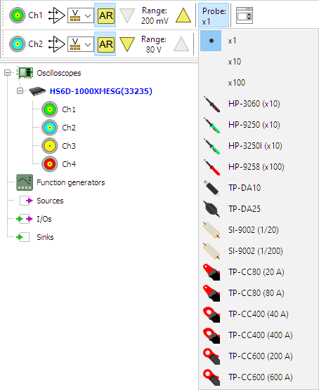
New Probe menu
A probe setting is added to the instrument channels. The probe setting allows to select the actual probe or current clamp that is used, which then sets the probe gain and unit to the required values.
The probe setting is available in the channel popup menu, on the channel toolbar and in the channel settings window. All TiePie engineering oscilloscopes probes, differential attenuators and current clamps are included in the menu.
Other changes
Several other minor changes and corrections have been made in the software, to improve controlling instruments and performing measurements.
- Icons in Object screen enlarged for better visibility and easier touch screen use
-
Graph:
-
A graph that was brought to its own window now has a
 Restore in main window tool button to restore it back in
the main window.
Restore in main window tool button to restore it back in
the main window. - Samples from a Data Collector I/O that are not yet measured, are no longer drawn, avoiding confusion.
-
A graph that was brought to its own window now has a
- Trigger settings dialog: Levels are now aware of channel probe gain and unit.
- Compression test sink : toolbar button for cylinder count added to dialog.
-
EMI I/O:
- 30 MHz added to the list of Fmin presets.
- BugFix: When displaying a logarithmic frequency axis and an Fmin <> 0 Hz was selected, the grid and the signal did not match with each other.
- Fix: When an EMI Quick Setup was loaded, the instrument toolbars were not properly hidden.
- Fix: In certain situations, connecting the second channel to a Pulse decoder I/O or an SPI decoder I/O was not possible.