April 13, 2021
Version 1.44 of the Multi Channel oscilloscope software is now available for download.
Various changes have been made to add new functionality and to improve basic operations in the software. This is a categorized overview of some of the changes.
Contents
- 1 New signal processing I/Os added
- 1.1 Phase difference I/O
- 1.2 RMS I/O
- 1.3 Slice I/O
- 1.4 I2C decoder I/O
- 1.5 UART / Serial decoder I/O
- 2 New features in settings windows
- 3 I/O creation menu divided in categories
- 4 New features for the Table sink
- 5 Easier zooming and panning in graphs
- 6 New probe settings for channels
- 7 Other changes
New signal processing I/Os added
A number of new I/Os have been added to the software, to help process your signals and get the most information from it.
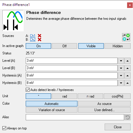
Phase difference I/O
A new Phase difference I/O is added to the software. It determines the average phase difference between two measured signals.
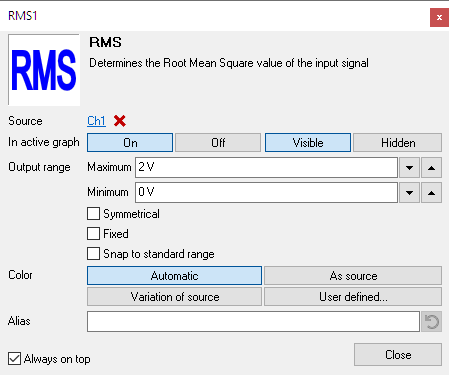
RMS I/O
A new RMS I/O is added to the software. It determines the Root Mean Square value of the measured signal. It can be used to log RMS values in the data logger.
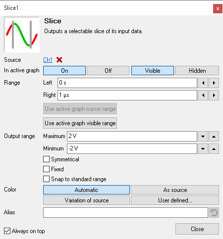
Slice I/O
A new Slice I/O is added to the software. It cuts a slice out of its input signal and removes the parts before and after the slice. A typical application of the Slice I/O is to remove unwanted parts of a measurement. If a long measurement was performed to capture a specific phenomenon which is (much) shorter than the total measurement, the Slice I/O can be used to remove the parts that are not interesting. The original time info is kept. This makes processing and saving the interesting part much more efficient.
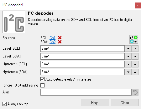
I2C decoder I/O
A new I2C decoder I/O is added to the software, replacing the existing I2C analyzer sink. The I2C decoder I/O decodes analog data on an I2C bus to I2C data. Just measure the Clock and Data lines of the I2C bus with a scope and connect the measuring channels to the I2C decoder I/O. The I2C decoder I/O has auto level detection and auto bus speed detection. The output of the I2C decoder I/O can be shown in a Table sink.
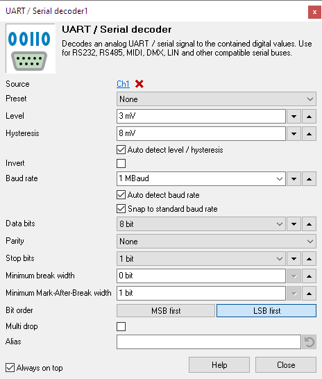
UART / Serial decoder I/O
A new UART / Serial decoder I/O is added to the software, replacing the existing Serial analyzer sink. The UART / Serial decoder I/O decodes analog data on a serial bus to serial data. It can be used to monitor and analyze UART, RS232, RS485, MIDI, DMX, LIN or other compatible serial buses. The UART / Serial decoder I/O has auto level detection and auto baud rate detection. The output of the UART / Serial decoder I/O can be shown in a Table sink.
New features in settings windows
Various new features are added to the settings windows for instruments, channels and I/Os.
-
Channels:
- A clickable link is added to open the settings window of the instrument the channel belongs to.
- Buttons are added to directly add a Filter I/O behind the channel, to simplify filtering the measured signal.
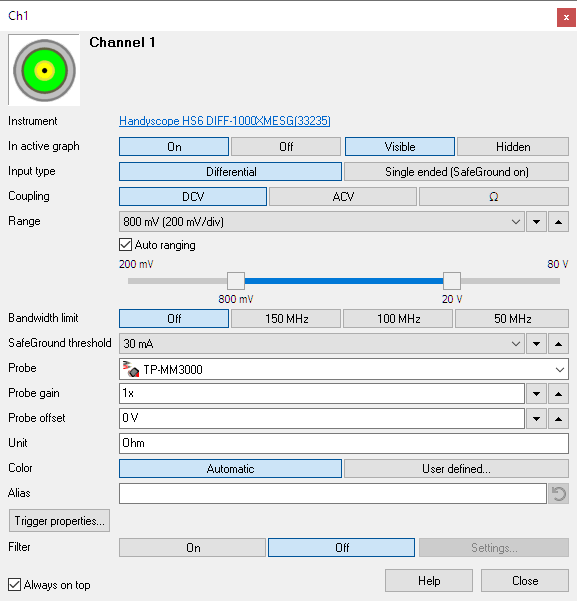
Figure 6: Channel settings window - I/Os: The source(s) of the I/O can now be connected and disconnected in the settings window.
- The Up / Down edit controls now have support for using the mouse wheel to change the value. The mouse must be located over the control.
-
Several settings now have a reset button , to reset the setting to a default value:
- Resetting the Alias field will clear the field, which will show the original name of the channel or I/O again.
- Resetting the Gain or Offset of a Gain / Offset I/O will set the Gain back to 1 and the Offset back to 0.
- Resetting the Skew of a Deskew I/O will reset it to 0.
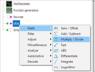
I/O creation menu divided in categories
The menu that is used to create I/Os in the Object screen is now divided in categories.
- Math : perform a basic mathematical operation on one or more signals
- Filter : perform a filtering operation on a signal or consecutive signals
- Adjust : perform an adjusting operation on a signal or consecutive signals
- Miscellaneous : perform an other operation on a signal or consecutive signals
- Analyze : analyze the input data and extract specific information from it
- Automotive : perform automotive specific operations on the data
- Decode : decode serial communication data from the input data and present the decoded messages
New features for the Table sink
Several new features have been added to the Table sink:
- When double clicking a row in the Table, the active graph zooms in at the part of the signal that corresponds to the table row. This makes it easy to locate a certain decoded message of a protocol decoder in the measured signal. Optionally cursors can be placed on the beginning and ending point.
-
The toolbar has been rearranged and new buttons are added:
-
 :
enables / disables data collection in the table
:
enables / disables data collection in the table
-
 :
place cursors on the beginning and ending point when double clicking on a row
:
place cursors on the beginning and ending point when double clicking on a row
-
 :
opens the column selection dialog
:
opens the column selection dialog
-
 :
Opens the source's settings window
:
Opens the source's settings window
-
- Specific support for protocol decoders is added regarding column alignment, column visibility and row colors
Easier zooming and panning in graphs
Horizontal zooming in graphs and then panning the signal is made easier by using the mouse wheel. Wheel up causes the graph to zoom in horizontally, around the location where the mouse is positioned. Wheel down causes the graph to zoom out horizontally, around the location where the mouse is positioned.
When zoomed in, the graph can then be panned horizontally by dragging the signal left or right, with the right mouse button pressed.
New probe settings for channels
The probe settings for channels have been expanded:
- A Probe offset setting has been added to compensate for probes and sensors that add an offset to the signal.
- The Milliohm Meter TP-MM3000 has been added to the probe menu
Other changes
Several other minor changes and corrections have been made in the software, to improve controlling instruments and performing measurements.
- All decoder I/Os and other I/Os handling "digital" signals now have auto level and auto hysteresis detection.
- Meter sink: Clicking on the source label of a meter display now opens the source's settings dialog (if the source has one).
- DiskWriter / Meter / Compression test sink: The dialog caption now also holds the source name(s).
- Updated Polish and Japanese translations.
-
Fixes:
- Fixed network search for WiFiScopes on Windows 10
- Fixed streaming with 2 x Handyscope HS6 DIFF combined, where no channels of second unit were used
- Fixed wrong unit for automatic measurements Max - Min and Top - Bottom with logarithmic signals
- Meter sink:
- Fixed time stamp when logging streaming data to disk
- Fix: When source is a Data collector, use only the actually measured data for the calculation
- Fixed interpolation in Graphs when the shown signal was only 1 sample long
- Fixed access violation when right-clicking a Filter I/O and an Ideal Filter I/O together in the Object screen.
-
Table sink:
- Fix: Always include header width in size calculation
- Fix: Let columns only grow when initial data is added
- Fixed a problem occurring in the Compression test sink when one cylinder was so bad it did not show any peak at all.